Making a powered Z-Axis table for my K40 Laser Cutter - Holgamods Kit (Part 3)
This is part 3 of the motorized Z-Axis build for my laser cutter
You can find part 1 here
You can find part 2 here
It has been about a week and a half since i last worked on this.. So I thought I should get around to finishing it this weekend.
I bought a new 13mm drill bit the other day and it was time to use it!

Each of the holes were marked by putting the frame onto the aluminium sheet and taping it down to it. Once taped onto the sheet, I then used a punch tool to mark where to drill the holes.
Unfortunately I didn't take any photos of this stage
So here is the first hole done.

All 4 holes drilled!

To make sure there were no sharp edges, I utilized my de-burring tool.

With a little bit of force, run the blade around the edges to de-burr them on both sides

On my trip to Bunnings today, I picked up some Fibre washers, M10 size. The Kit came with some 3D printed washers, however someone... ok me.. damaged them. So these will work nicely

With the brass nut all the way down, I put a washer on each corner. This will be used to ensure epoxy doesn't drop down (shown later)

Put some washers between the screws and the 3D printed holder for the motor

And here i Thought I was done with this stage... Until I remembered the limit switch...

There is a 3D printed limit switch holder that came with the kit, so I drilled out some 3mm holes and then tapped them to 4mm and then screwed this in with 4mm screws

Installed the Limit switch with 3mm bolts onto the mount


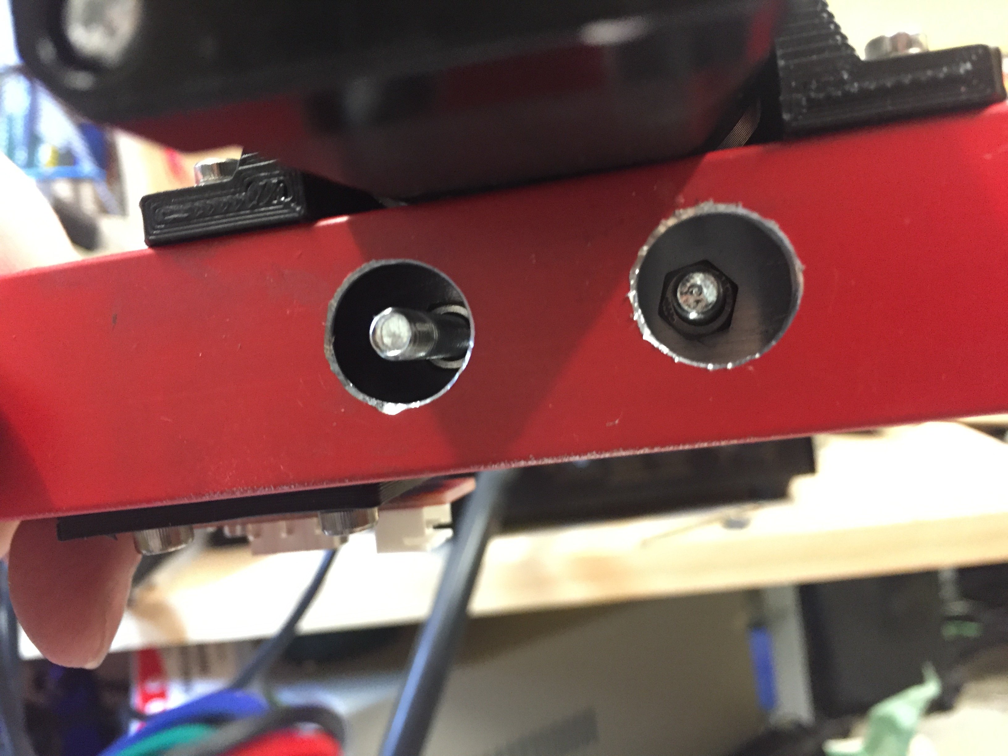
While I put the limit switch on, I couldn't get the drill in easily to make the holes, so I removed the bar int he middle temporarily, and noticed that the screws for the bearings had come loose.. So I reversed the nut and put a washer on the bottom. This means that the surface area on the baring is only touching the middle part, and so movement will no longer twist the hole screw out

I did the same for the ones near the motor, except I also added a 5mm nut underneath after drilling a hole in the bottom
Ok we are now back to this stage, with the limit switch installed and the idler pulleys fixed

So I place the sheet of aluminium onto the top of the brass nuts. Seems my holes were not perfectly lined up when I drilled them... luckily I drilled them larger so they had enough clearance anyway

You can see the Fibre washer underneath

Here is some Araldite (5 minute) Epoxy adhesive. Those tubes are a gimmick from this brand that allows you to apply the epoxy directly to the part, and the two parts combine together down the tube. Handy for this!

Here is the applicator installed

Applied epoxy into the gaps of each corner, making sure that it filled in the gaps to form a bond with the brass nut and sheet

Once epoxy has been applied, then these little half washer thingos that came witht he kit sit on top and get glued at the top


The next part will be installation into the actual K40 Laser Cutter.
I have new lens mounts and and mirror mounts that Im also installing, so I have to get that part done first.. With the mounts I bought, I am going to have to raise the first mirror and the tube a little bit, so that It can all align up.. I'll post that up when its done :)
This post has received a 11.87 % upvote from @booster thanks to: @rativiv.
Join our Discord Channel to connect with us and nominate your own or somebody else's posts in our review channel.
Help us to reward you for making it ! Join our voting trail or delegate steem power to the community account.
Your post is also presented on the community website www.steemmakers.com where you can find other selected content.
If you like our work, please consider upvoting this comment to support the growth of our community. Thank you.