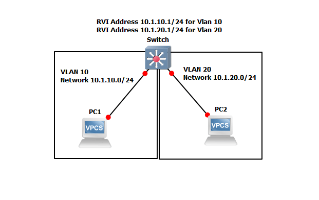
JunOS Switch Routed VLAN Interface (RVI) L3 Interface
Virtual LANs (VLANs), by definition, divide a LAN’s broadcast environment into isolated virtual broadcast domains, thereby limiting the amount of traffic flowing across the entire LAN and reducing the possible number of collisions and packet retransmissions within the LAN. For example, you might want to create a VLAN that includes the employees in a department and the resources that they use often, such as printers, servers, and so on.Of course, you also want to allow these employees to communicate with people and resources in other VLANs. To forward packets between VLANs, you normally you need a router that connects the VLANs. However, you can accomplish this forwarding on a switch without using a router by configuring a routed VLAN interface (RVI). Using this approach reduces complexity and avoids the costs associated with purchasing, installing, managing, powering, and cooling another device.
Why Should I Use an RVI?
In addition to providing communication between VLANs, an RVI binds specific VLANs to specific Layer 3 interfaces, allowing you to track RVI use for billing purposes. Configure an RVI for a VLAN if you need to:
- Allow traffic to be routed between VLANs.
- Provide Layer 3 IP connectivity to the switch.
Creating an RVI
- Configure VLANs—Virtual LANs are groups of hosts that communicate as if they were attached to the same broadcast stream. VLANs are created with software and do not require a physical router to forward traffic. VLANs are Layer 2 constructs.
- Create RVIs for the VLANs—The switch’s RVI uses Layer 3 logical interfaces on the switch (unlike routers, which can use either physical or logical interface).
- Assign an IP address to each VLAN—An RVI cannot be activated unless it is associated with a physical interface.
- Bind the VLANs to the logical interfaces—There is a one-to-one mapping between a VLAN and an RVI, so only one RVI can be mapped to a VLAN.

Create VLANs 10 and 20. Click here to Learn Create VLANs.
root@Switch#set vlans VLAN-10 vlan-id 10
root@Switch#set vlans VLAN-20 vlan-id 20 Create RVIs for the VLANs
root@Switch#set vlans VLAN-10 l3-interface vlan.10
root@Switch#set vlans VLAN-20 l3-interface vlan.20 Bind the VLANs to the logical interfaces
root@Switch#set interfaces vlan unit 10 family inet address 10.1.10.1/24
root@Switch#set interfaces vlan unit 20 family inet address 10.1.20.1/24 After configuration check connectivity.
Source: – Juniper.net