Tutorial: How to Replace Step Down Circuit in 12V Power Supply | Easy DC to DC Converter Setup.
Assalamu alaikum Everyone. I am @imranhassan From #Bangladesh
A few days ago I made a 12-volt power supply. I have a concern; I will start a project with a 555 timer IC, so I could not start it yet due to some repair work on my hand. I have now decided to start my project, so I will need sometimes 5 volts, sometimes 9 volts and sometimes 12 volts to do small projects.
So I had a fixed 12-volt power supply, which could not be set to the voltage to run the project with my IC, so today I am going to share with you a module that can be stepped down from 12 volts to 1 volt. Let's see how to do it step by step.
Step -01
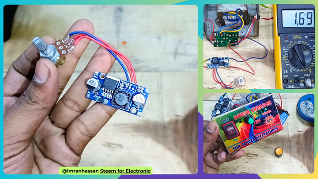
Now the power supply that you see in my hand is a 12-volt DC power supply or battery charger that I made earlier. Today I will replace the DC-to-DC step-down voltage circuit inside this power supply.
Step -02
Now the model number of the circuit that you can see in my hand and everything I have shared in my video – you can watch the video if you want – and here I have put a variable. 10k resistance so that I can step up and down easily from the outside.
Step -03
Now you can see that I have removed the casing of my 12-volt power supply, and inside you can see the transformer and DC circuit. Basically, from here I will replace the circuit with the output.
Step -04
In this step, first I took two pieces of wire because to make the output connection, I have to make the connections with wire.
Step -05
Now you can see that the DC output line of my power supply was taken earlier. I have shown you the DC output above 16 volts through a digital multimeter. From here I will take the output again, and the previous output will remain here.
Step -06
Now you can see that I have put 17 volts of input voltage into the step-down voltage circuit.
Step -07
Now in this phase I will need two pieces of wire again to take the output connection from the step-down circuit because from here I will have to use the line to reduce and increase the voltage of my various projects.
Step -08
Now you can see that I have connected the yellow and red wires on the output side of the voltage down circuit; now my complete connection is complete.
Step -09
In this step you can see that after completing the circuit, I am again checking the output by turning it through the digital multimeter, and here you can see that when I turn it and reduce the output through the variable resistance, my digital multimeter is showing 1 volt, which means that my circuit and replacement are complete.
Step -10
Now I have tested the power of the circuit by running a 12-volt DC motor, and I have reduced and increased everything, and it is fine, which can be seen well in the video. The video is given below. You can watch the video if you want.
Step -11
Now I have replaced it with a variable resistance casing so that I can reduce and increase it from the outside and work on my project with the voltage I need, and the purpose of putting a variable resistance in the circuit is so that I can control it from the outside.
Step -12
Now you can see that I have taken out my yellow and red colour wires from a hole in the front because the reason for bringing this connection to the front is that when I work on projects with small parts, it will be very good for me if this line is in front because I will put a meter here so that later I can work on the output by looking at the meter.
Step -13
Now you can see that after all my connections are complete, after putting on the body cover, I have glued the output that I took out so that the wires do not move. Then I have given power here, and you can see the output on the digital multimeter, so if you want to see the output decreasing and increasing, I have already said that you have to watch the video.
And when I made this power supply earlier, in the post I said that I would bring another tutorial post from this power supply for the purpose of the post I have posted today. I will give the link to the post where I made the power supply earlier here, and from there you can make a power supply if you want., and from today's post and from the video, you can replace this circuit if you want, and later I will put a digital meter here; you are invited to do that.
| Video Tutorial: To better understand the practical part of this tutorial, you can watch the video below. |
|---|
✅ CC: My friend @rmm31
✅ We support @pennsif and @pennsif.witness for the growth of this platform. pennsif.witness his contribution to the Steemit community. Vote for him as a Witness here: Click to Vote
| Photography Details | 📱 Device: Walton Xanon90 | 📍 Location: Narayanganj, Bangladesh | 📷 Captured By: @imranhassan |
|---|
.png)


Congratulations... I have recommended this post to get support from Steemchiller and Realrobinhood.
Alhamdulillah, I was very happy when I woke up this morning and saw the votes.
https://x.com/ImranHosen98536/status/1976331765217464431