S19-Wk2: Electronic component measurement and measuring instruments.

Snapped with Nokia C30)
Measurement and Measuring Instruments
In our previous lesson, we identified some basic electronic components, discussed their functions and their circuit symbols. Today we are taking a step forward. In this week's workshop task, I will show you some facts about analog multimeters and how they are used to test and measure some of the components we identified in the previous workshop exercises.

| Type | Analog |
|---|---|
| Brand | Sunwái |
| Model | YX-360TR |
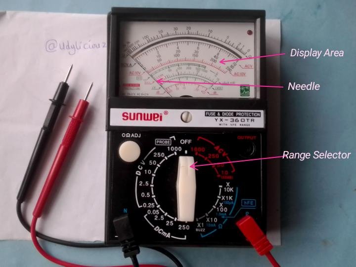
This analog multimeter has fuse and diode protection, powered by two AA battery, has 3 input sources and the output is displayed in an analog format with a needle over a graduated scale.
Component Testing
[ 1 ] Fuse

| Component | Fuse |
|---|---|
| Test Function | Continuity |
| Rating | 250V 13A |
| Range | No range |
| Probe Setting | Com and Positive |
| Orientation | None Polarized |
Procedure
Step 1
Set meter function to continuity as indicated in this picture

Step 2
Connect the test probes to the metal ends on both sides of the fuse
Observation
The continuity indicator LED is on, the buzzer is blazing and the needle has made a full swing.

Test Conclusion
Fuse is in good working condition
[ 2 ] Resistor

| Component's Name | Resistor |
|---|---|
| Test Function | ohmmeter |
| Rating | 1000Ω |
| Range | x1k |
| Probe Setting | Com and Positive |
| Orientation | None Polarized |
Procedure
Step 1
Set meter function to ohmmeter and range to x1k as indicated in this picture

Step 2
Use the test probes to touch the metal on both sides of the resistor, and avoid touching the resistor during reading.
Observation
The display needle has moved close to number 1 on the scale, it was expected to stop at 1 which could make it 1kΩ hopefully the tolerance should cover for the shortage.

Test Conclusion
The resistor should have been 1000Ω, but now it is a little less. The resistor is good.
[ 3 ] Variable Resistor
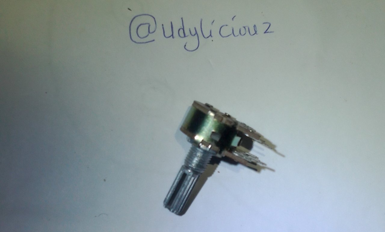
| Component | Variable Resistor |
|---|---|
| Test Function | ohmmeter |
| Rating | 0-10kΩ |
| Range | 10kΩ |
| Probe Setting | Com and Positive |
| Orientation | None Polarized |
Procedure
Step 1
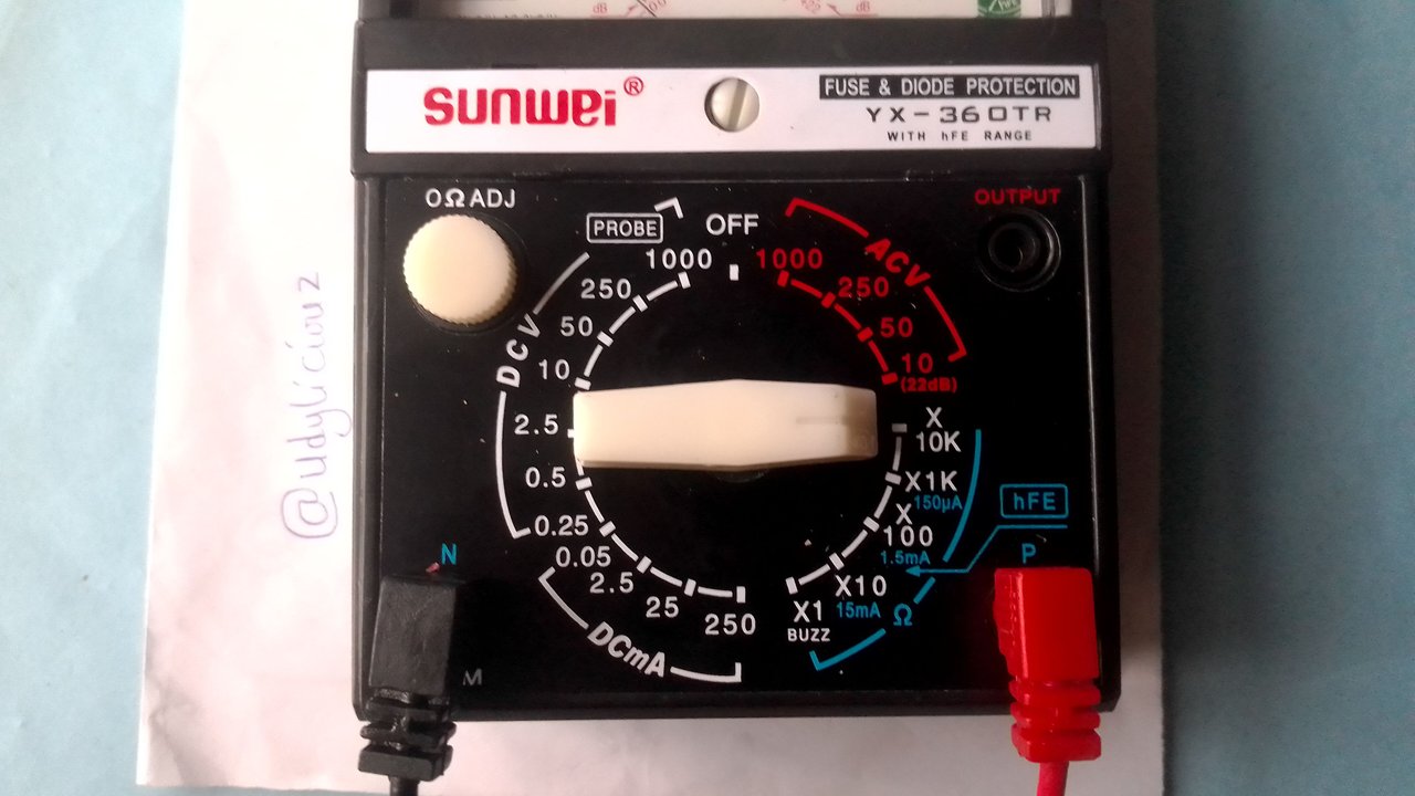
Set meter function to ohmmeter and the range to x10k is indicated in this picture
Step 2
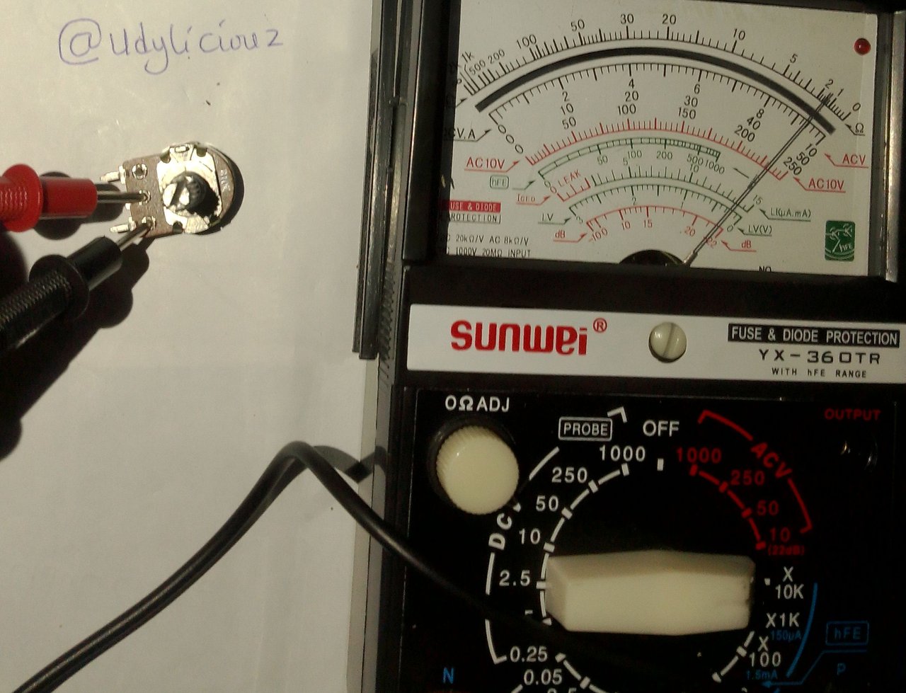
Connect one of the test probes to the metal at the center and the other probe to another hole. You can switch places during the test.
Observation
At its highest point the value of this resistor is 20k and at its lowest point it's resistance is 10k
Test Conclusion
The test result indicates that this variable resistor is not fit for work.
[ 4 ] Alternating current Voltage

| Component | ACV |
|---|---|
| Test Function | ACV |
| Rating | 240 V AC |
| Range | 250 AC V |
| Probe Setting | Com and Positive |
| Orientation | No Polarity |
Procedure
Step 1
Set meter function to AC V and the range to 250 as indicated in this picture, be very careful because it is high voltage.

Step 2
Connect the test probes in to the outlet holes, it will not matter which of the two holes because it has no polarity.
Observation
The meter is detecting 170 volts of alternating current
Test Conclusion
The supplied voltage is low some appliances will need a stabilizer to step it up.

[ 5 ] Direct Current Voltage

| Component | DC V |
|---|---|
| Test Function | DC V |
| Rating | 3.8 V |
| Range | 10 |
| Probe Setting | Com and Positive |
| Orientation | Polarized |
Procedure
Step 1
Set meter function to DCV and the range to 10 as indicated in this picture

Step 2
I am testing a phone battery. The red test probes must be connected to the terminal of the battery marked with a + sign and the black connects to the battery terminal marked -
Observation

This battery is outputting 2.5v of direct current, the display needle was expected somewhere close to 4
Test Conclusion
This battery is not in good shape or may have been drained.
[ 6 ] Capacitor

| Component | Capacitor |
|---|---|
| Test Function | ohmmeter |
| Rating | 400v 82uf |
| Range | x10k |
| Probe Setting | Com and Positive |
| Orientation | Polarized |
Procedure
Step 1
Set meter function to ohmmeter with it's rage at x10k as indicated in this picture below
Step 2
Connect the positive test probe to the positive terminal of the electrolytic capacitor and the negative probe to the other terminal.
Observation

The capacitor caused the display needle to move towards zero then came back to where it started.
Test Conclusion
This is not the best way to test a capacitor but can tell if it is not totally bad. This one is useable.
[ 7 ] Light Emitting Diode

| Component | LED |
|---|---|
| Test Function | Continuity |
| Rating | |
| Range | No range |
| Probe Setting | Com and Positive |
| Orientation | Polarized |
Procedure
Step 1
Set meter function to continuity as indicated in this picture below

Step 2
Connect the test probes to the metal connectors on the LED, the LED is a Polarized component so the positive test probe must be connected to the correct side to get result. So if you get no results, switch sides by reversing the probes.
Observation

When the test probes are reversed, the LED turns off
Test Conclusion
This LED is in good condition.
[ 8 ] Coil

| Component | Coil |
|---|---|
| Test Function | continuity |
| Rating | - |
| Range | no range |
| Probe Setting | Com and Positive |
| Orientation | None polarized |
Procedure
Step 1
Set meter function to continuity as indicated in this picture
Step 2
Connect the test probes to the metal ends on both sides of the coil
Observation

The coil is a couple with two wires and 4 terminals, each wire has a good continuity
Test Conclusion
The test is only able to tell that the coil has continuity
Tools for workshop exercises:
Thess are some of the tools that will be used in our workshop exercises.
Desoldering Pump

We will use this with a soldering iron when desoldering components from a printed circuit. It sucks out the melted lead from the mounting holes, making it easy to remove the component.
Veroboards

We will use the veroboard to try some prototype circuits. It can also be used for the final product.
Project Board
The project board will be used when making a quick prototype circuit that will not need lead and soldering. It is very good for new students.
Pliers

The pliers will be used to hold items, loosen some bolts, and twist cables.
Screwdriver set

We will use screwdrivers to open into electronics devices to work inside them.
Insulating tape

Cable endings will need to be insulated using this PVC tape to avoid shock and bridging.
It has been interesting to learn more and practice with a multimeter as a test instrument. I am thankful to all instructors in the Electronics Academy for giving me this learning opportunity, which I plan to take full advantage of.
I am inviting @bossj23 and @eliany and @simonnwigwe
Here is the link to the assignment
https://steemit.com/hive-188837/@ubongudofot/s19-wk2-electronic-component-measurement-and-measuring-instruments
Hiciste todas las mediciones solicitadas, las explicaste de manera detallada facilitando la lectura con un cuadro, esto le ha aportado estética a tu trabajo.
A pesar de que tú multimetro no cuenta con la medición de capacitancia, hiciste la prueba del capacitor electrolítico en la escala de resistencia para comprobar la carga y descarga. Esto lo hacen los técnicos que no se limitan y que solo buscan soluciones.
Comment/Recommendation
En la tarea 2 mencionaste unas 3 herramientas realmente útiles para las próximas clases, pero no visualizaste lo que pudiera venir y solo te limitaste a tus herramientas, herramientas útiles, pero que no se enfocaron en lo que estamos trabajando o hacia donde queremos llegar con las clases. Debes empezar a pensar más como técnico, sí no contabas con esas herramientas pudiste mencionarlas y describir que se podría hacer con ellas.
Scores| 8.5/10
Thank you for the review and corrections, I will start thinking like an electrician and wish to do better in subsequent lessons.
Te veo entusiasmada y así debes seguir hasta el final, date tu tiempo para organizar tus próximas tareas y luego participar.
Upvoted. Thank You for sending some of your rewards to @null. It will make Steem stronger.
Thank you ma'am @ngoenyi for the support
https://twitter.com/udyliciouz/status/1814634412065104112?t=19b5GGyPCwKf3bO5LRfG2w&s=19
With the help of the teacher's post and with the help of your measurements I learn a lot. Now I get a new knowledge about electronics. I am an IT student now I am interested in electronics too. I also did my job to participate. Your hard work must pay off. I wish you more success.
Greetings from my side. Have a nice day
I am glad my post was helpful to you. I am not expert in the field just like you. But since learning never stops, I keep learning though it took me somw days of trying before I could finish it. I am glad I did. Thank you for visiting my article.