PX-16C assembly
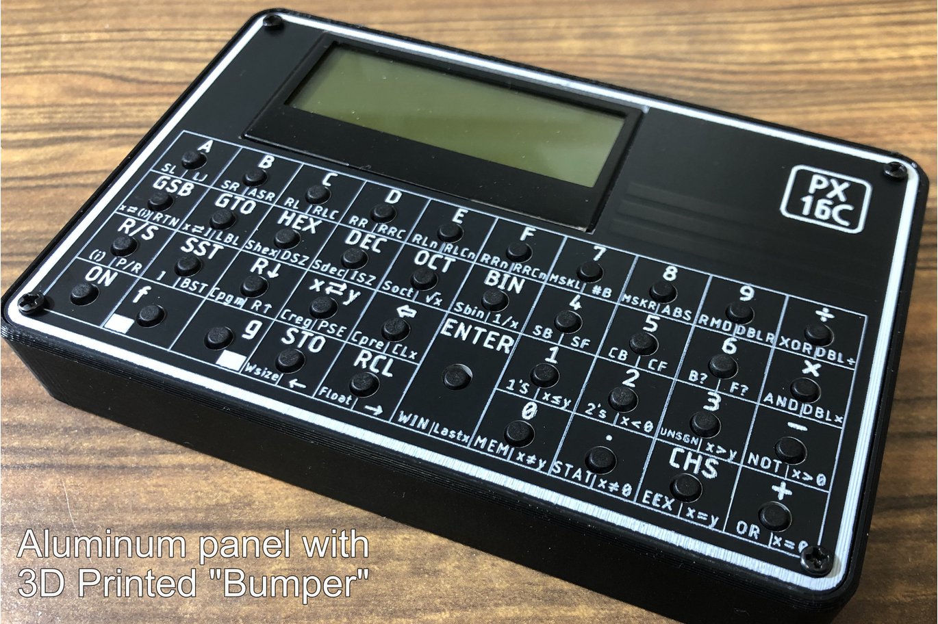
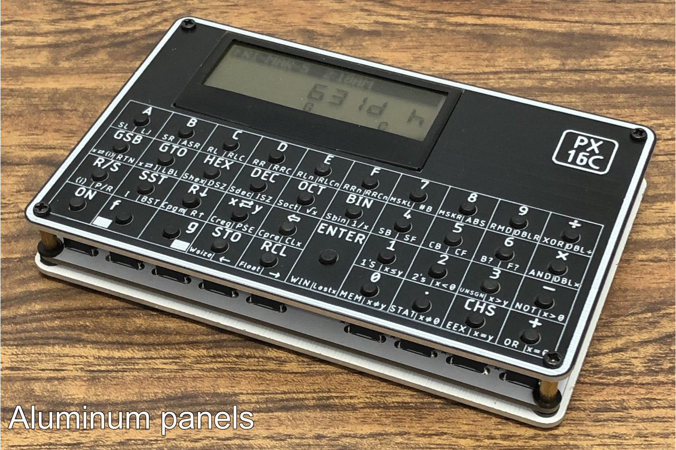
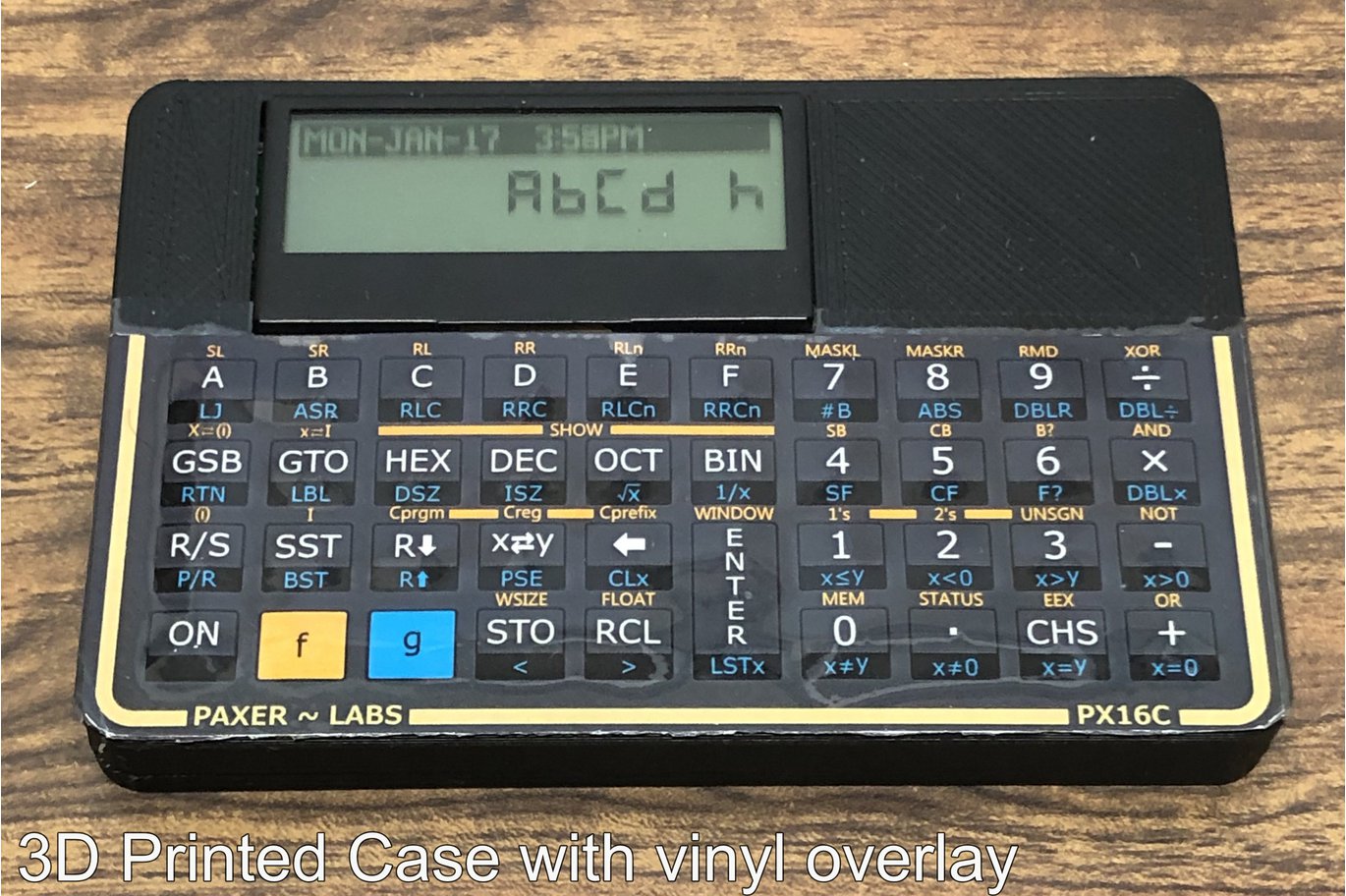
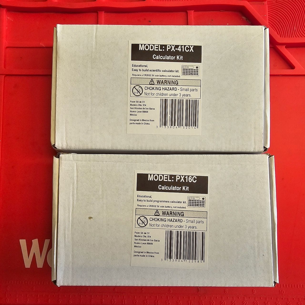
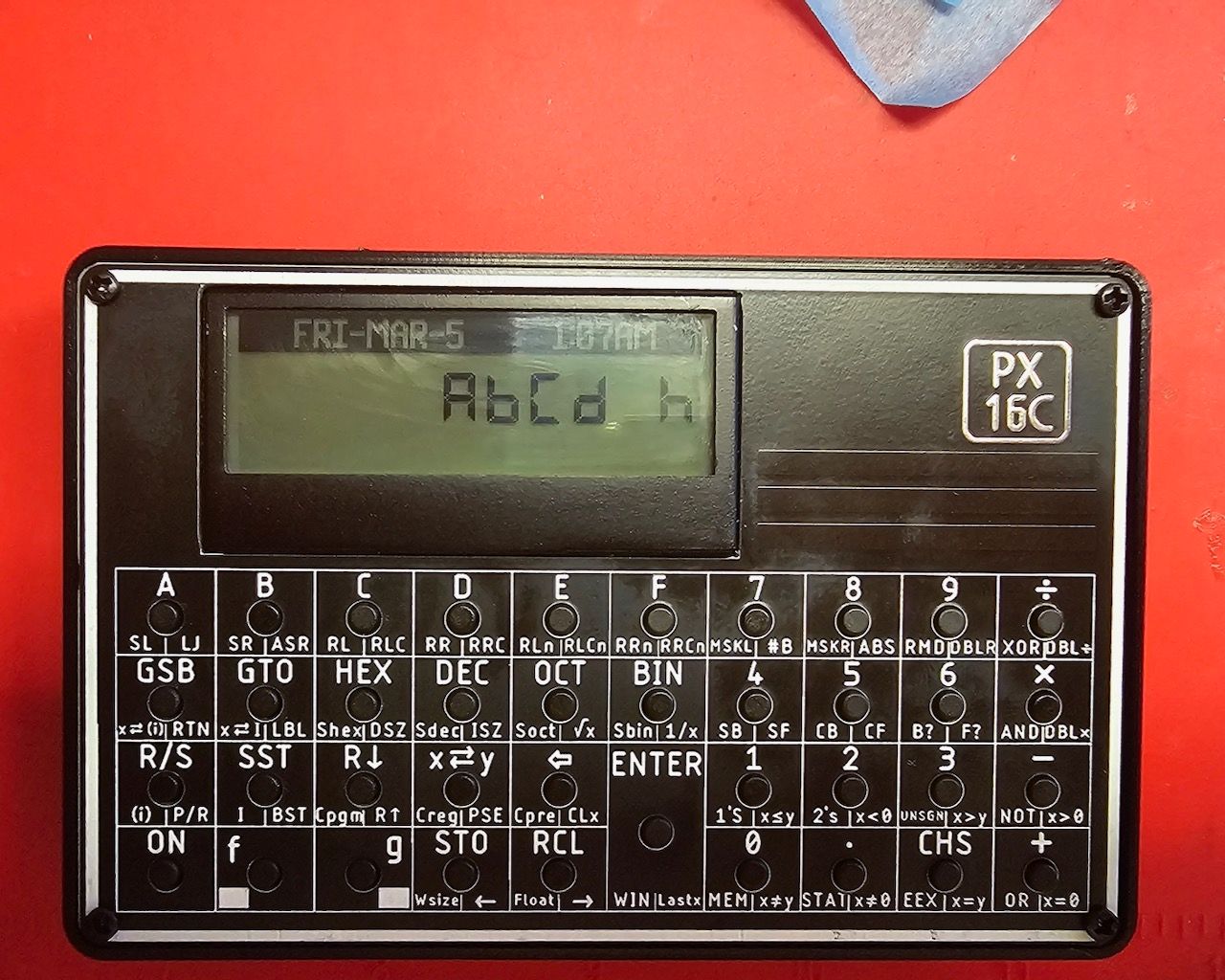
The PX16C is a replica of the classic HP-16C programmers calculator. Unlike the Swiss Micros replicas DM16 and DM16L the PX16C comes a kit for self assembly which makes the PX16C significantly cheaper then the DM16L. I wend for the version with tall switches, the aluminium front and back planes and a 3D printed bumper.
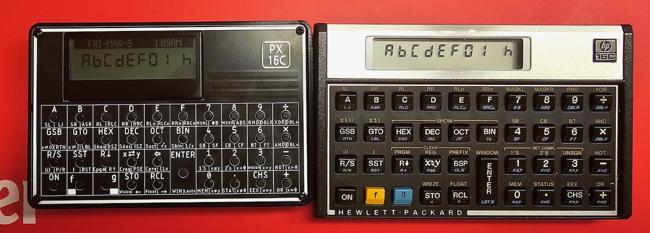
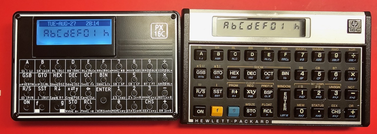
There is also a version with short switches and a 3D printed case. Here the models, inclusive the SwissMicros to compare.
 |  |
|---|---|
 | 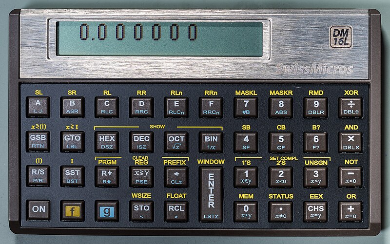 |
There is not doubt that the SwissMicros does looks better and more like the original but it's also three times the price.
 | |
|---|---|
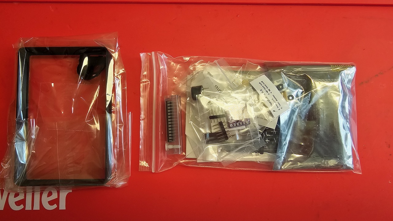 | 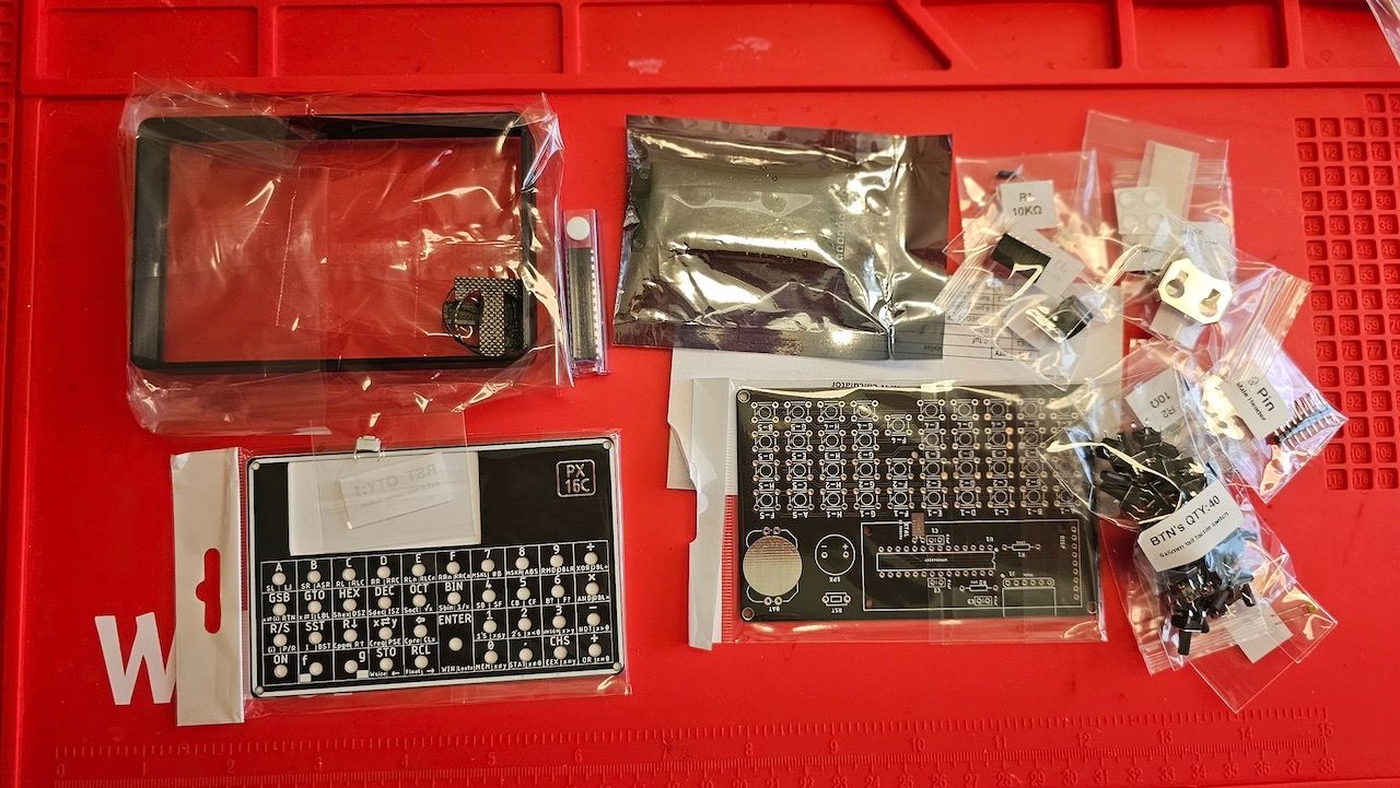 |
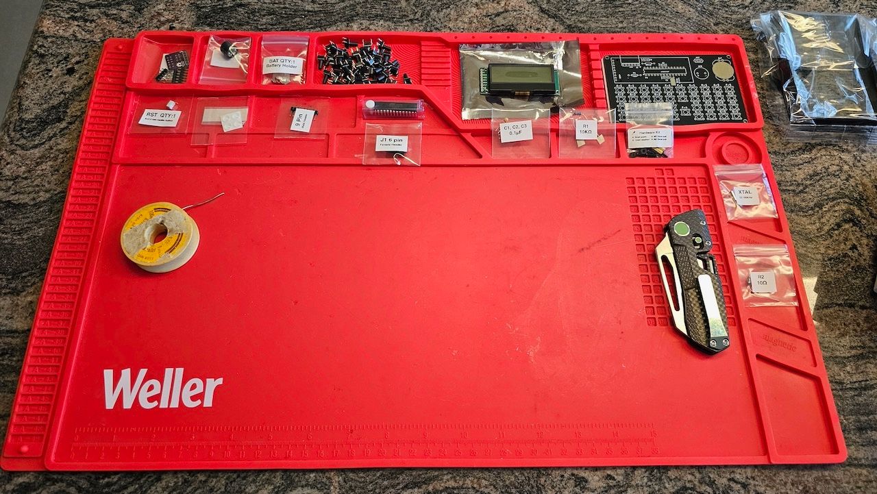
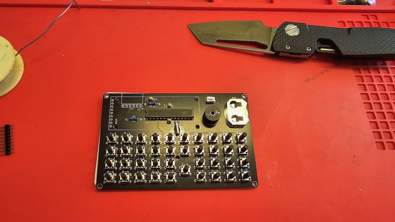
Following the instructions the soldering and electronic assembly was quite straight forward:
 |  |
|---|---|
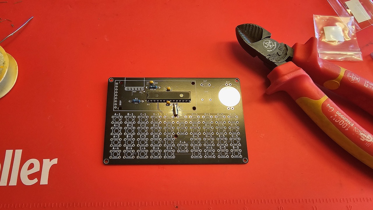 | 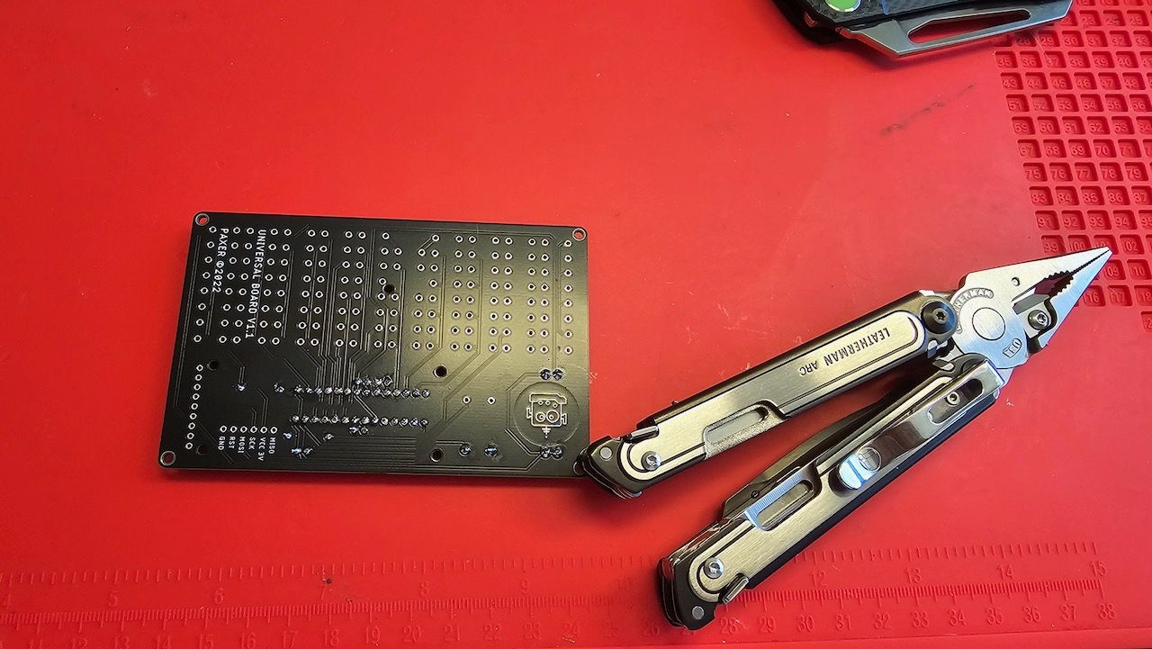 |
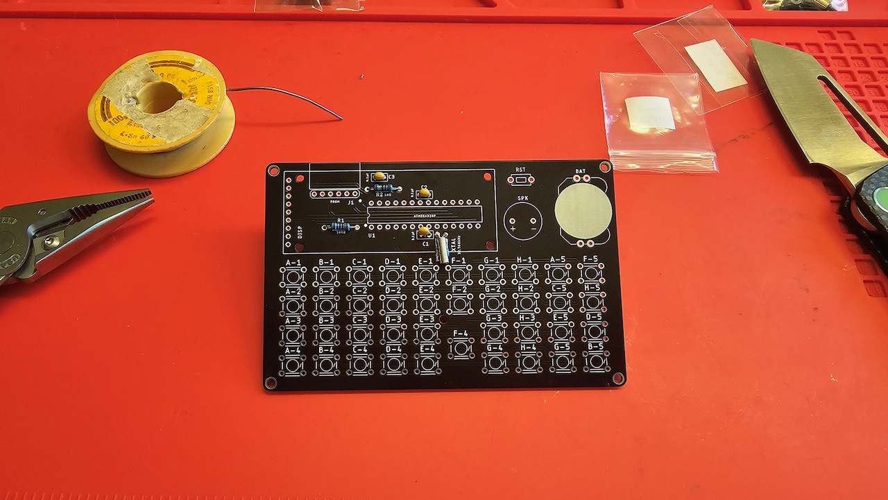
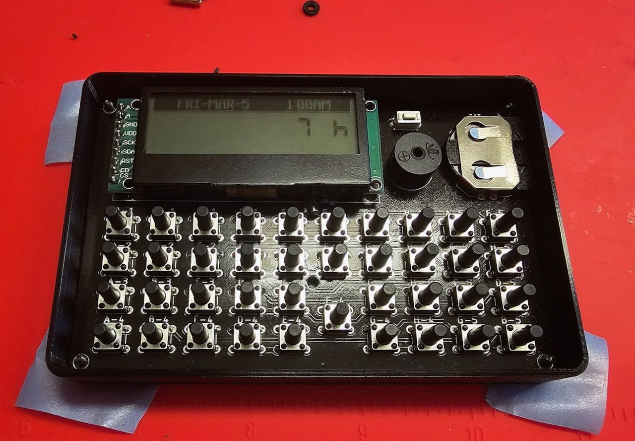
I used the Leatherman as a weight to keep the battery clamp in place. When placing the switches it's advisable to use the aluminium front plate as guide — if you added the aluminium plates to your build.
 |  |
|---|
At this point I made a significant mistake. I missed that there are different instructions for building with and without the 3D printed bumper:
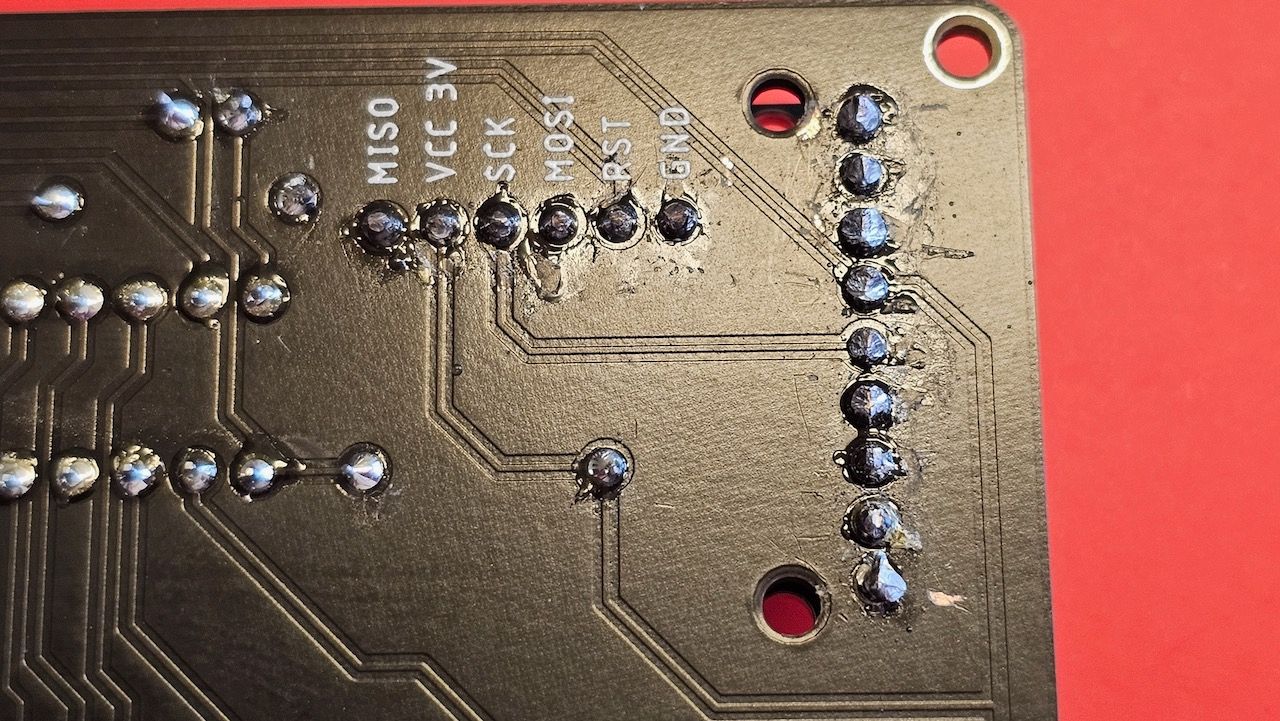
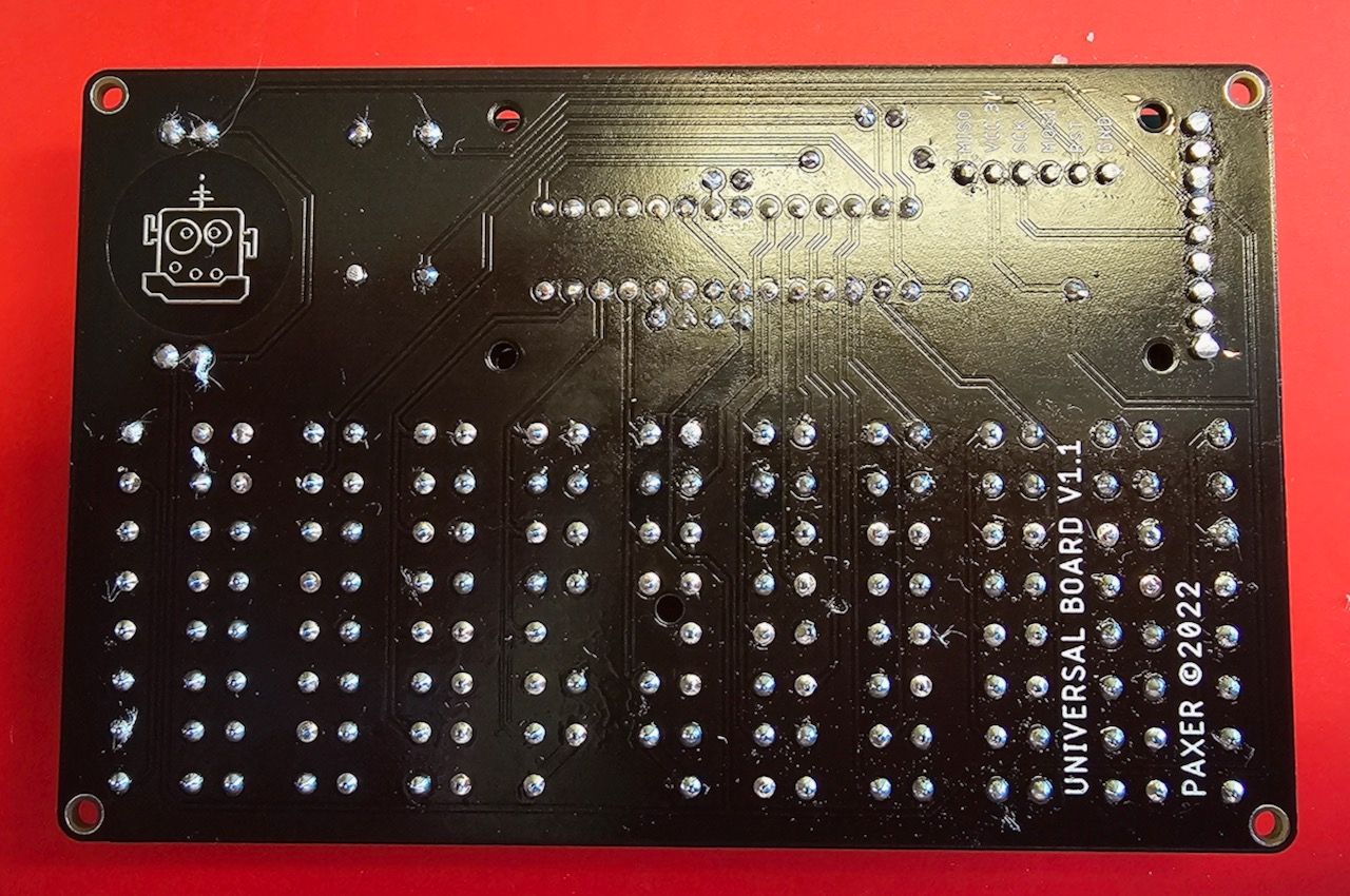
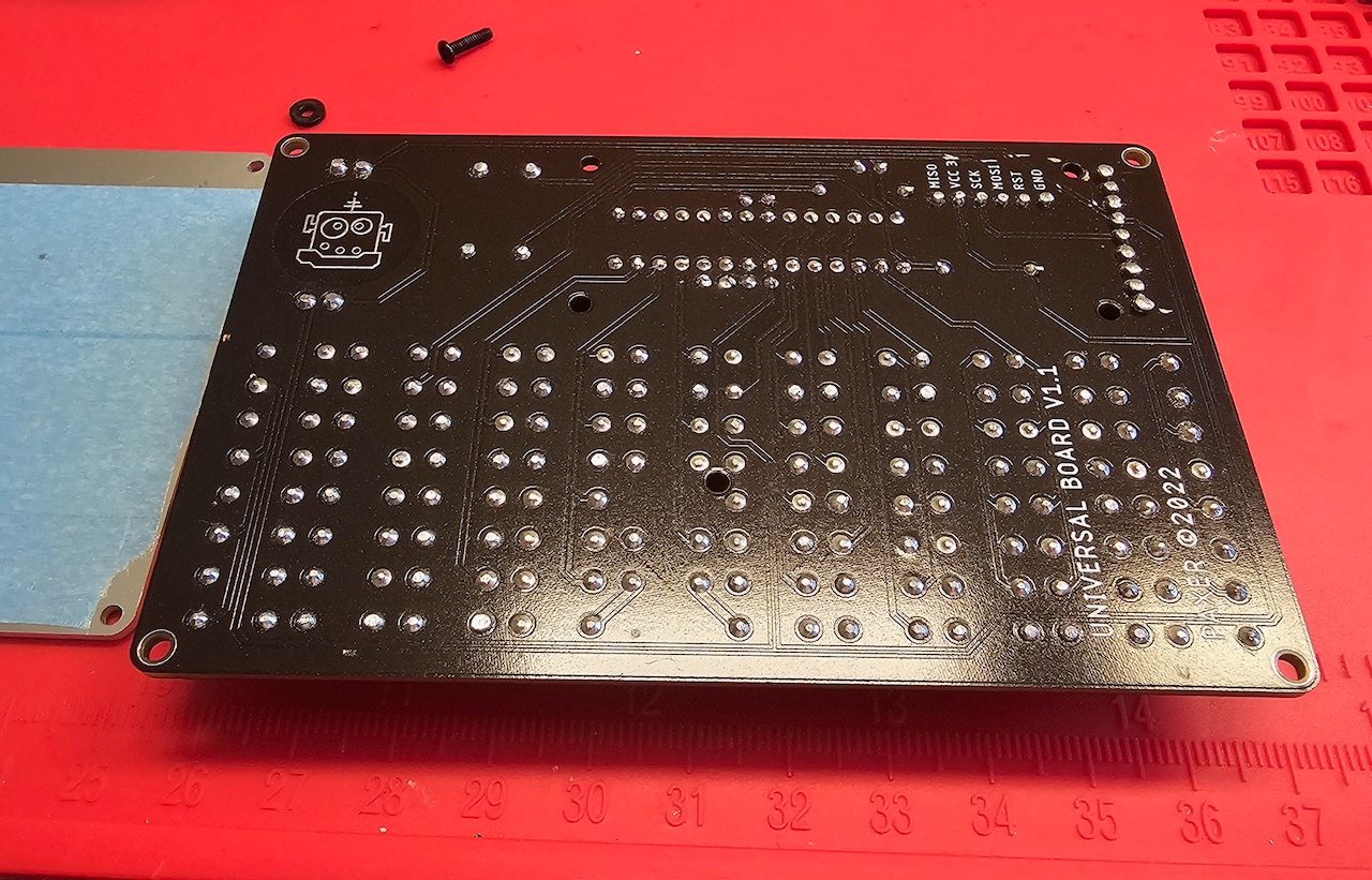
Following the wrong instruction lead to much confusion. Apart from that the greatest challenge are the extreme tight tolerances between the PCB and the aluminium back plate need to be cut down to 1 mm. Normally I'm quite generous with the solder but this time that was a mistake. Use as little solder as possible as it will make cutting down the wires that much easier.
In order to make it work I used masking tape on aluminium back plane and Dremel to grind down the soldering points. You need a cone shaped grinding stone and remember that a Dremel is unforgiving. If you slip that's it.
 |  |
|---|---|
 |  |
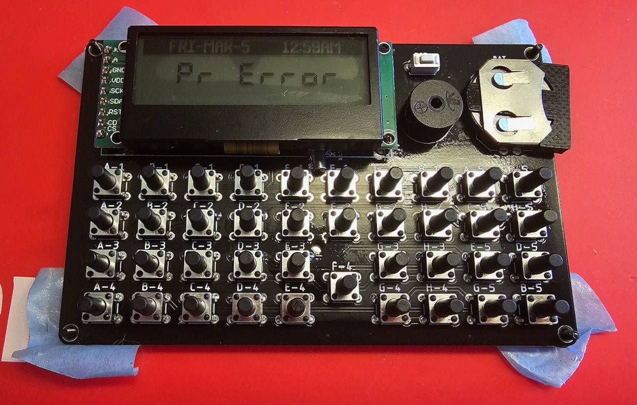
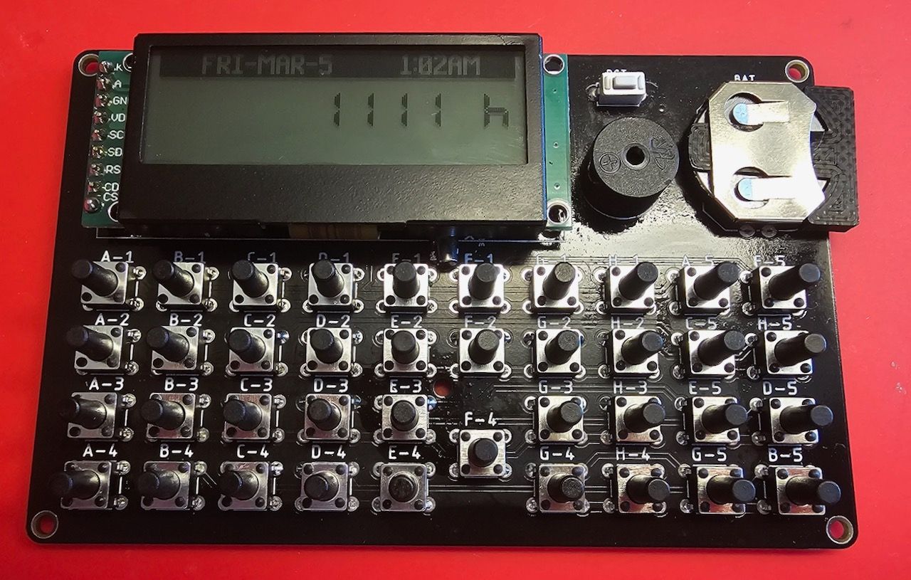
At one point the project seemed to have failed. When testing I only got as far as „Pr Error“ which can normally be cleared with a press on the «⇐» (aka clear) key. My test procedure is:
- Insert battery — „Hello!“ is displayed.
- Press «ON» — „Pr Error“ is displayed.
- Press «⇐» — „0 h“ is displayed.
- Do a small calculation to test the keys.
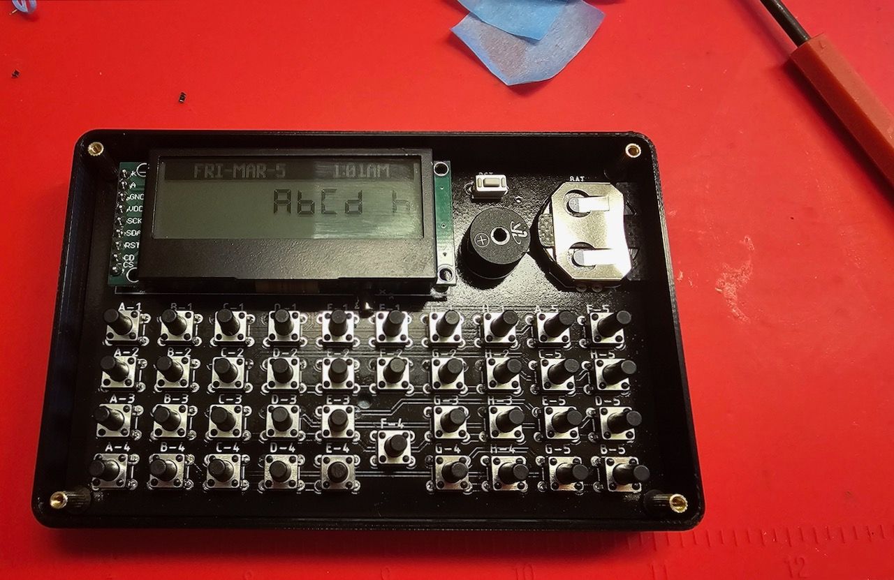
After more though cleaning and involving air blower and blow drying (used to much electronic cleaning spray) the calculator was back to live. That was quite the fright as I already thought the project failed.
 |  |
|---|
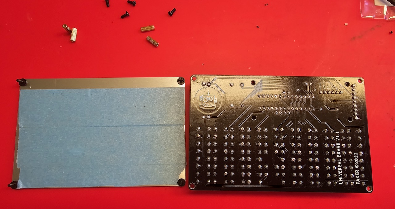
On one of the picture you can see that I used masking tape to fix screws. Using Tape
 |  |
|---|---|
 |  |
Note that on upper right picture I added the nylon washer. But those are not needed with newer build and I had to remove them later. This opened an interesting alternative. As you can see on the lower half picture the back plate is fairly deep in the case. I later added the washer between the back plane and the case effectively doubling the space between PCB and back plane. If I had known that earlier I could have same some grinding.
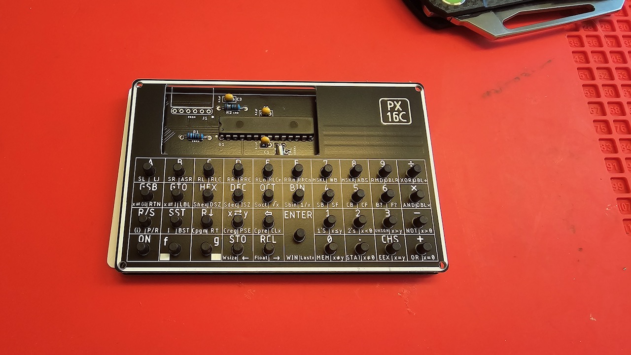
The actual calculator is is just a bit taller then then original original but smaller in the other two dimensions.