Computer Logic Gates Made Easy
Logic Gates
A logic gate is an electronic circuit capable of making logical decision in a binary system where The state of the input or output signal of a logic gate is represented using zero and one, true and false, a high or a low...
They are basically designed using diodes, though transistors and integrated circuits can also be used in making logic circuits.
A logic gate can be expressed using any or all of the following:
-a truth table
-a logic diagram
-a boolean expression
Truth Table
A truth table is a table containing all possible input combinations for a specific logic gate and their corresponding output. Every logic gate has a truth table
Logic Diagram
A logic diagram is a distinct diagram used to represent a specific logic in an electronic circuit or schematic diagram.
Boolean logic Expression
This a programming or mathematical statement that produces a true or false result according to a specific logic gate.
Basic logic
There are three basic logic which can be combined to create other secondary logic. The primary logics are the 'NOT Logic' the 'AND Logic' and the 'OR Logic' each logic has a distinct characteristic, a logic circuit and a truth table. All logics must have a single output while only the NOT Logic comes with a single input, every other logic can have two or more onputs but still has only one output which can only produce a zero or a one as it's result.
The NOT Logic
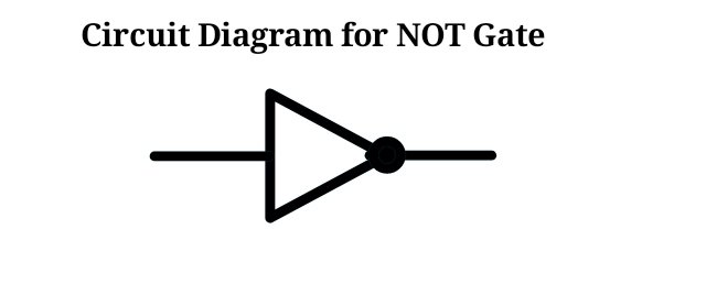
The inverter or NOT Logic is a Negation logic that has a single input and a single output. It produces an output that is a direct opposite of what it received as input.
Logic Diagram for NOT Logic

Truth Table for NOT Logic
| Input | Output |
|---|---|
| 1 | 0 |
| 0 | 1 |
The NOT Logic has only one input which results in only two possible inputs and two corresponding outcomes. When ever the input is one then the output is zero and when the input is zero the output is one.
Boolean Expressions for NOT Logic
NOT A = A'
NOT A = Ā
The AND Logic
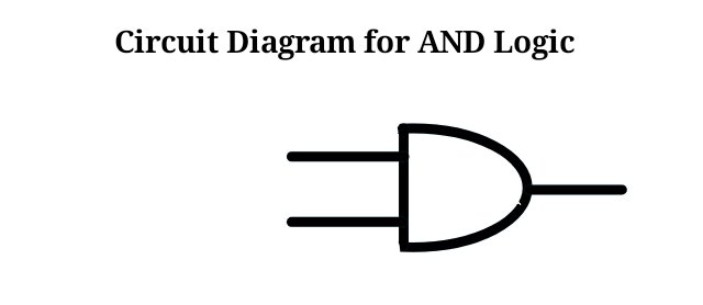
The AND Logic is a logic with two or more inputs having only one resulting output. It is a Logical conjunction that only produces a value 1 when both inputs are one. So all inputs must agree to have a an output of 1.
Logic Diagram for AND Logic

Truth Table for AND Logic
| Input x | Input y | Output |
|---|---|---|
| 0 | 0 | 0 |
| 0 | 1 | 0 |
| 1 | 0 | 0 |
| 1 | 1 | 1 |
Boolean Expressions for AND Logic
A AND B = A ^ B
A AND B = A . B
The OR Logic
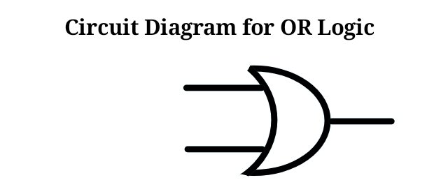
The OR Logic is a Logical disjunction with at least two or more inputs producing a single output who's state will be 1 if at least one input is a 1, so will only be a zero when all inputs are zeros.
Logic Diagram for OR Logic

Truth Table for OR Logic
| Input x | Input y | Output |
|---|---|---|
| 0 | 0 | 0 |
| 0 | 1 | 1 |
| 1 | 0 | 1 |
| 1 | 1 | 1 |
Boolean Expressions for OR Logic
A OR B = A v B
A OR B = A + B
Conclusion
We shall create secondary logic by combining some of this logic to form more complex logic in my next post.
10% to steemalive

@uby4real, you have really proven you have almost a complete knowledge of computer as if you wrote it, I admire this ooo, congrats
We appreciate the valuable information you have shared in this post. Keep sharing high quality posts on Steem-alive community
Remark
Great post.
You've got a free upvote from witness fuli.
Peace & Love!