SLC21/WK1: Introduction to Basic Electrical Hand Tools & Measuring Instruments.
It's actually my first time working with the equipment used for this course. I've been used to working with bulbs, pliers and screwdrivers before the introduction of these testers. I've been seeing people use these testers and readers but don't really give consideration or focus into what they do. Sometimes students ask why we learn all these theories and principles in school as if we would use them in making money.
Yes, this knowledge, theories and principles are used extensively in every aspect of the house when it comes to connectivity, appliances, light even solar etc; Without our knowledge of these theories and principles especially their applications, i doubt we'll be able to make a lasting impression in this field of study.
Most times, the theories don't help when applications aren't made that's why you see graduates come out without knowing certain applications like wiring a house or even checking current and volt. I'm no professional in this field but have basic knowledge as to parameters like voltage, current, resistors, live and neutral wire etc.
Irrespective of the fact that I'm not a professional but not a novice doesn't stop me from carrying out these practical but with extra caution and safety. My safety tools were kept in place to carryout these practicals, starting with the identification of some tools and equipment used in the electrical field.
Identify the electrical tools in the picture and mention the name and function. |
|---|
The picture above is the first task we are told to do, which is the identification of the tools and electrical equipment shown. The equipment is actually labelled with numbers for easy identification. I'll take them as they are arranged, from top to bottom, to avoid mixing up numbers.
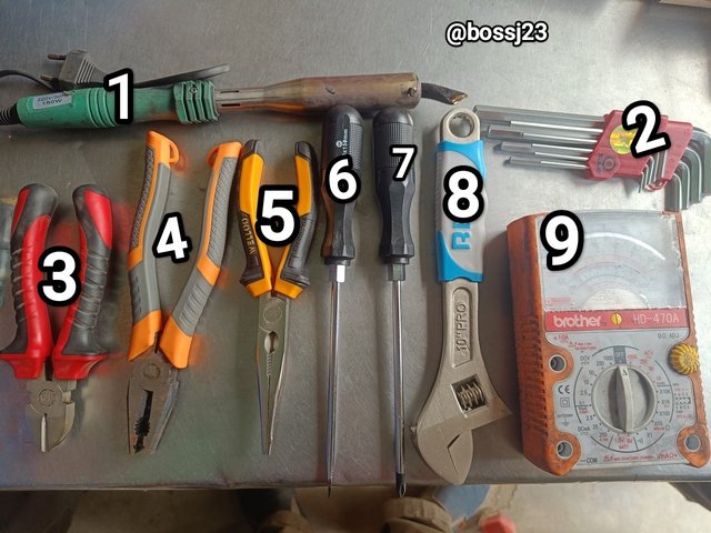
picture sourced from contest @mahadisalim
1
- Soldering iron: How can a novice identify this tool? A soldering iron is a powered electrical tool for electronics. It's a tool held with the hand and used for joining two metal components together by melting what we call solder, which is a metal alloy that's fusible. If you notice in all these chargers, radios, DVDs, and phones's circuits, you'll see that there's a white metal alloy that holds the wires in place. These white substances are melted by the soldering iron and used in connecting wires, capacitors, circuits, etc. As the name implies, it produces heat when plugged into a source of electricity, and this heat is used to melt that metallic alloy used for joining wires on circuits.
To identify a soldering iron is easy. Just look at the picture; it has a plastic handle with a metal body or bottom. The metal body is cylindrical, like the tool used in removing knots from heavy equipment. Underneath it is the slender or funnel top that pushes the heat to the solder when placed on top of it. It has an electrical wire on its top.
2
- Hex wrenches: Is the second tool labelled in the picture? It is an L-shaped tool used to tighten and loosen screws and bolts that have hex heads. It is mostly used in the repair of cars, electronics, and bicycles, as the case may be. It is identified easily from the shape it attains, which is L, and this makes it possible for grip by whoever uses it. It also has six tips that fit into the hexagonal sockets; that's why it's called keys because it looks more like a key's bunch.
3
- Cutter: This is a tool that looks more like scissors, or should I say shears. It has a handle with rubber coating to avoid electric shock, and it has a metal mouth, so to speak, that's more plane and sharp like a scissor. The only difference is the curvature and length of the blade. The blade is short and curves like a parrot's mouth. It is used for cutting and trimming wires, cables, etc.
4
- Pliers: It looks very much like the cutter as it has a rubber coated handle and a metal bottom. The curvature in the cutter is not seen in pliers, and these pliers aren't plain in terms of their blade. Plier has jaws and a small hole in-between the jaws. This is what I use in identifying that it's a plier. It's used for trimming wires in some cases, holding objects, turning wires, and bending them.
5
- Needle-Nose Plier: It's a plier replica but has different physical features. As the name implies, its blade is needle-like while it has this rubber-coated handle. It differs from the main Plier because it can go into the most narrow places to hold objects and bend them. The normal Plier can't go into such narrow places because of its size. So the difference is in the size.
6
- Flat screw driver: This is identified with a rubber handle and a slender body with a flat tip, which is used in loosening knots that have a straight line across their heads. This particular type of screwdriver fits in perfectly.
7
- Star-like screwdriver: It performs the same function of loosening knots. It's just that while the tip of the previous is flat, this one is star-like, and it fits into knots that have star-like heads.
8
- 10-inch Adjustable Spanner: It's different from the normal spanner that's static. It's used for tightening and loosening nuts of different sizes; that's why it's adjustable. It's also used to twist and grip objects.
9
- Analog Multimeter: This is an analogue multimeter and not a digital one because of the presence of a needle pointer that deflects around the scale, showing the readings. It doesn't have an LCD screen that shows the reading. This makes it analogue. It's used for checking or measuring the voltage, current, and resistance in a circuit and continuity.
These are the 9 tools identified. If you're a novice and you find it hard to identify when seen in a workshop, just take note of the observable features as explained to know.
Suddenly, the power supply to your house has been cut off. As an electrician, do the following:
Check the presence of electricity in your home with a neon tester. |
|---|
To do this comfortably, I took on precautionary measures to avoid stories that touch the heart. The neon tester is more like a screwdriver with a flat head and looks like a pen as its strings are covered with plastic. Inside this plastic, there's a bulb. I won't completely say it's plastic because it's just like some of these pen containers that look like glass. The essence of using this tester is to check the presence of electricity flowing in a current filled wire, socket, or circuit.
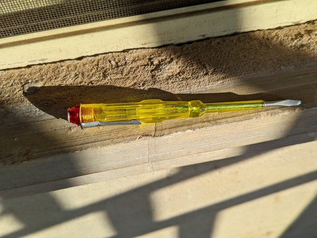 | Neon Tester |
|---|---|
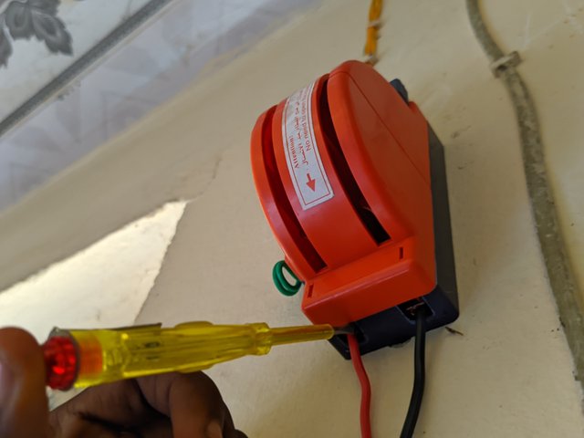 | Sample |
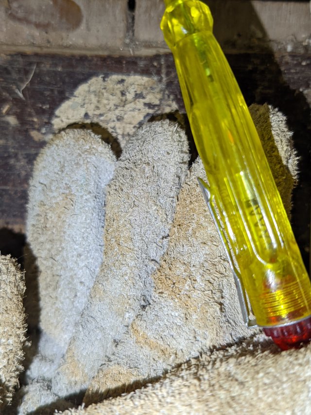 | Protective gloves |
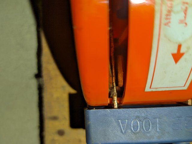
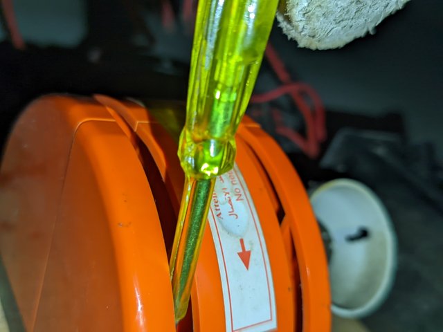
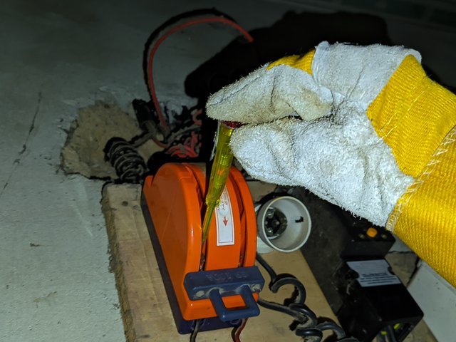
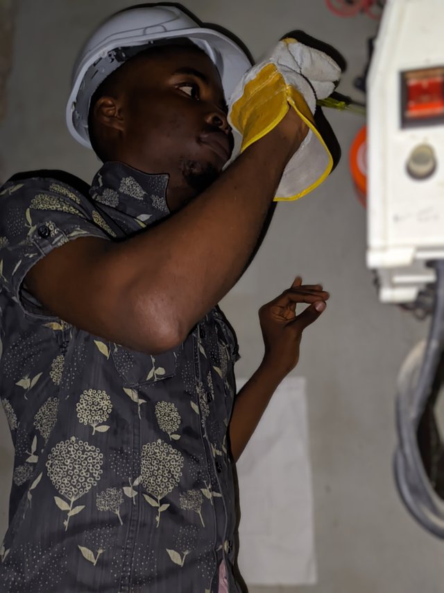
I made use of my gloves and helmets to prevent electric shock, though cases of such barely happen for the use of this tester. I took my neon tester, went to my changeover as it was already in light mode, and then placed the flat head of the tester on the metal iron inside the changeover circuit base, and the light reflected on the tester, indicating there was electric current there.
When using this neon tester, your finger must cover the top opening where the spring protrudes so you can get the question as to if current is there or not. Why cover?
 |  |  |
|---|---|---|
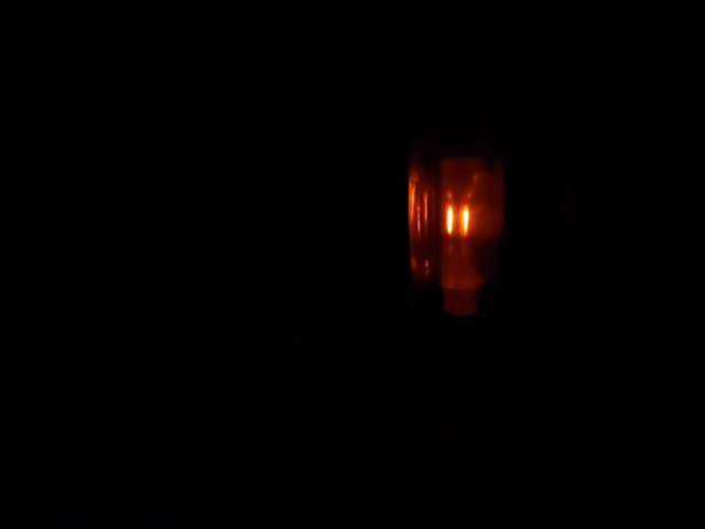 | 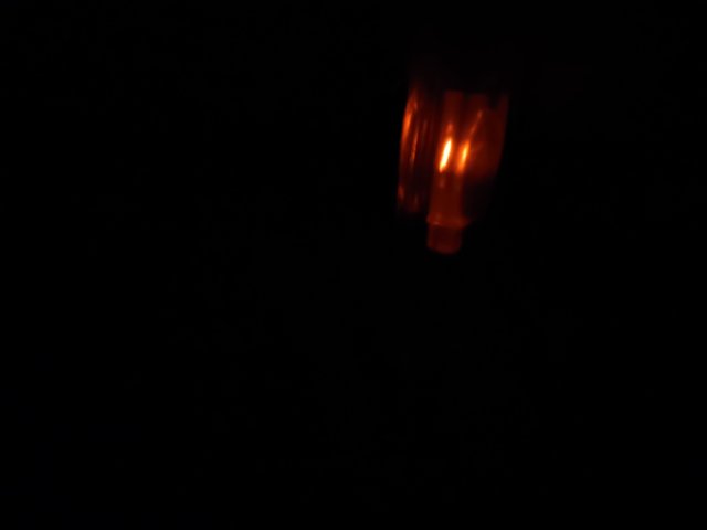 | Light shows in the lamp as I cover the end |
It is because covering the head prevents me from possible accident shock and also aids reading. Covering it helps you know if there's current, but in a situation where it's not covered, the lamp won't shine.
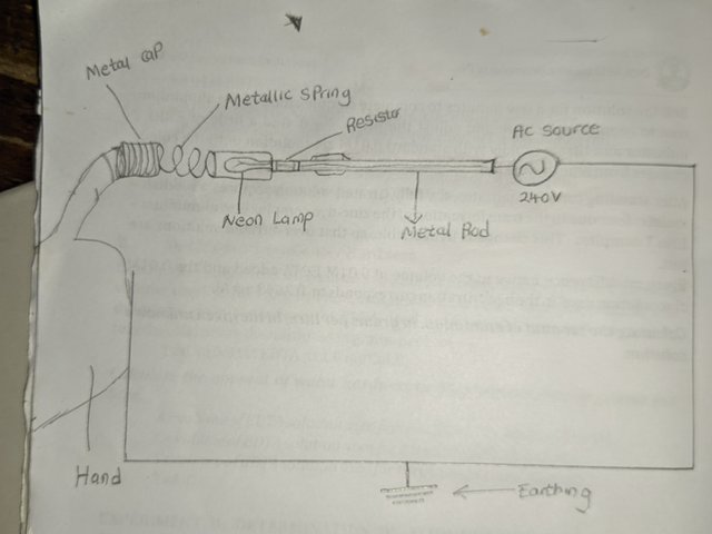
How this is illustrated diagrammatically.
If you notice on the drawing, you'll see the tester has a metal iron that connects or touches another metal iron, one that's in a circuit where current is following and there's an alternating current that has a number of volts in it. So putting the metal inside a socket to touch the internal metal places that sharp contact, and there's a connection of current.
Measure your home supply voltage with a multimeter |
|---|
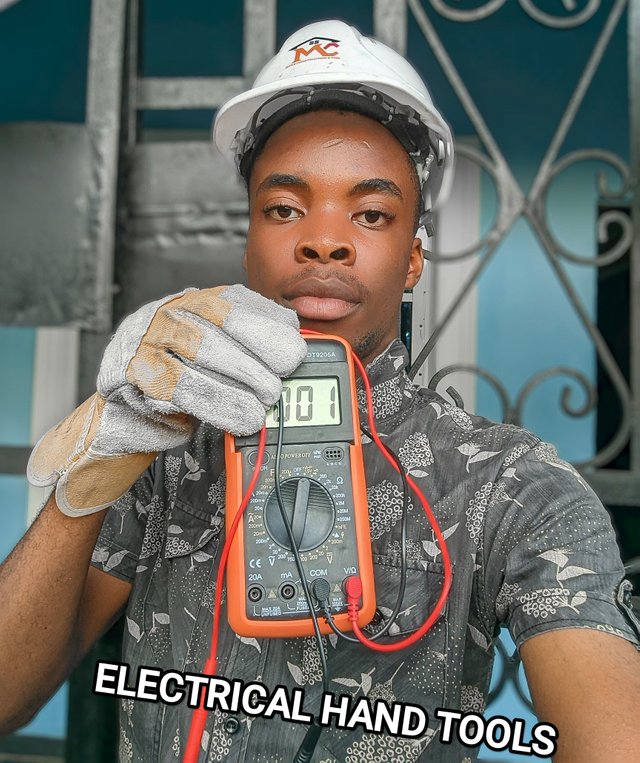
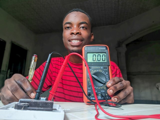
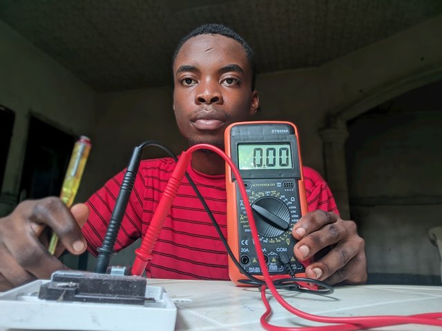
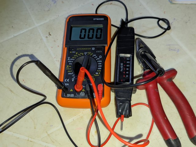
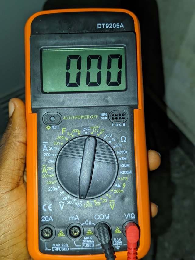
I'll solicit to use a voltmeter in checking this as my multimeter was faulty. The multimeter I have is a digital multimeter, as there's an LCD screen that shows the readings of voltage. There's also the presence of settings to check for current, resistance, and voltage, not just voltage. Wrong settings could lead to wrong readings; that's why it's always advisable to check the settings before using the probes.
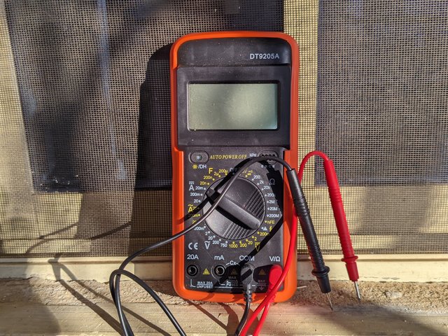 | Faulty Multimeter |
|---|---|
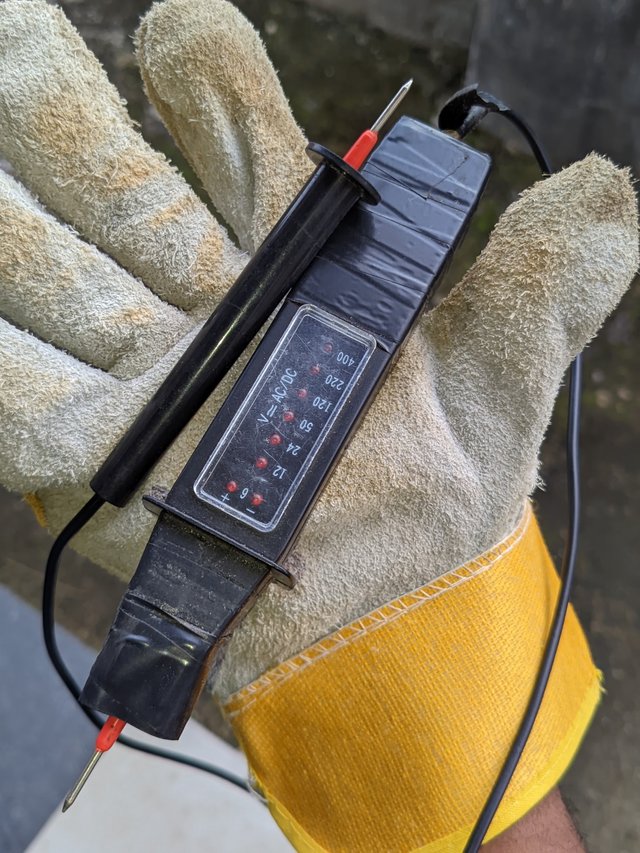 | Voltmeter |
A multimeter has two probes with plastic handles and iron tips. The probes are red and black and are usually placed in the hole labelled COM and V/Ohms.
- The black is placed in the COM hole since it's labelled as common; the short form of COM ensures the meter measures the voltage that is relative to the ground since black represents ground potential.
- The red hole is the hole that carries measurements and allows voltage and resistance of current in a circuit to be measured.
These two probes are placed on live wire on a circuit to check the voltage flowing as the readings would be reflected on the LDC screen. If it were good, I would have set it very well for use. In the absence of a good multimeter due to an error on the battery and an internal fault, I took to using a Duspol led 400 model which is more like the multimeter but has readings on the body.
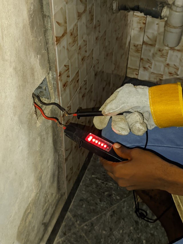
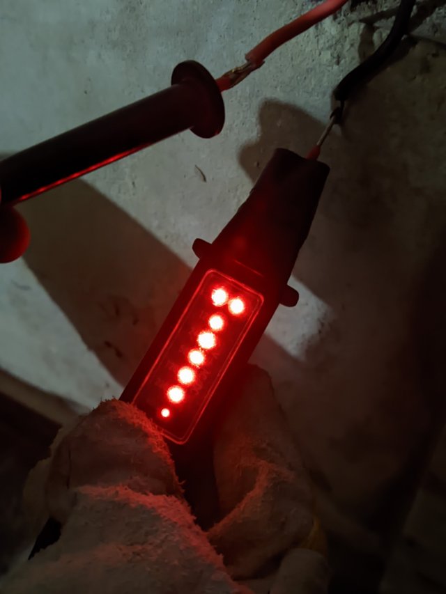
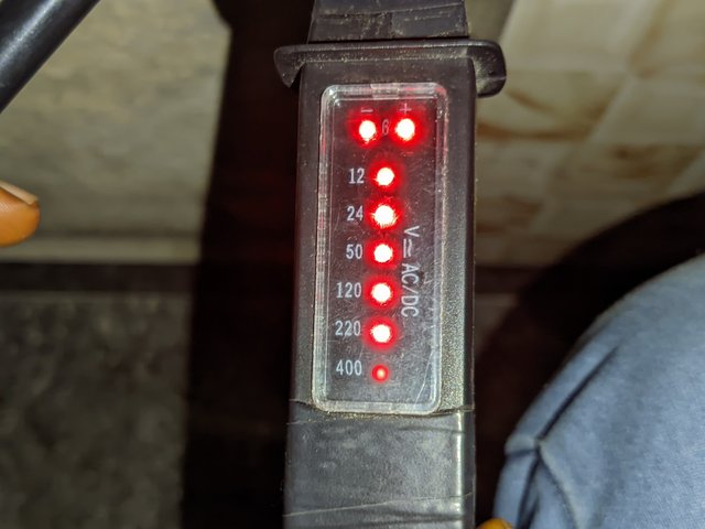
This Duspol led 400 model has a head probe and a tail probe—two in one, I mean. It has readings from 5V to 400V. When placed on wires or in a socket or circuit, a red light reflects in the bulbs. Wherever the red light stops is where the range of the voltage reading is. If it stops at 150, it means the voltage has a range of 150V. It doesn't specify the exact volt that flows, which a multimeter is better at. So since it was able to get this right, I moved on to the application.
Before measuring the voltage, I took on safety first by wearing my safety gloves as touching the wire bare hands when there's presence of electricity is a death sentence.
Gloves
Helmet
Shoe
I wore these to prevent casualties that may arise from electric shock. I then took my Duspol voltmeter with the probes and placed it on the live wires I wanted connected to a single socket to check, and the light stopped shining brighter at 200 volts, which means the voltage is good.
So the voltage in my home should be within the range of 200 volt to 240 volts which are standard volts that are good. There's is no specification using a voltmeter. Only the range is given.
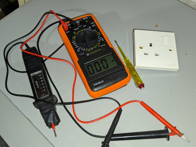 |  |
|---|---|
 | 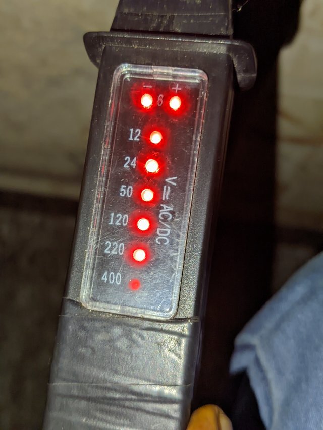 |
If it stopped at 400 volts, it would have been bad, as such voltage is due to problems in the power source and mostly from electric poles, high tension, etc. I was done measuring my volt using the voltmeter in the absence of a multimeter; that's good.
Complete the electrical wiring of a multi-socket and show us step by step. |
|---|
I also solicit my using a single socket due to the unavailability of such in my region and the cost elsewhere. So I used a single socket to demonstrate how it can be wired.
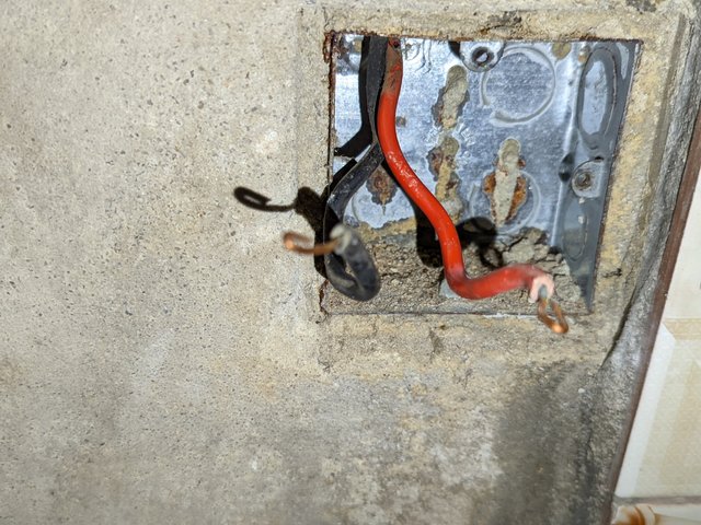
- First of all, you can't connect a stationary home socket when there's no connection of wires via poles to where you have the socket hole. If this is not done, you can use the manual as much as the two wires [Red and Black] are used for the connection.
 |  |
|---|
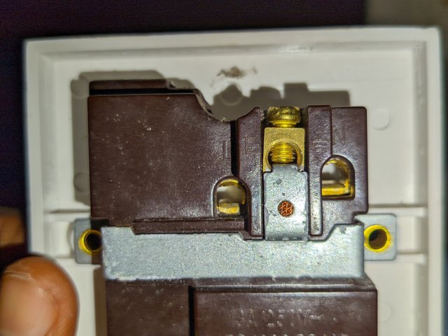
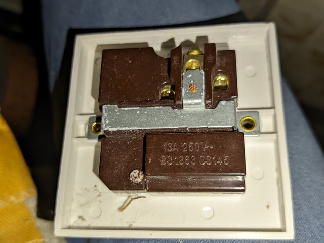
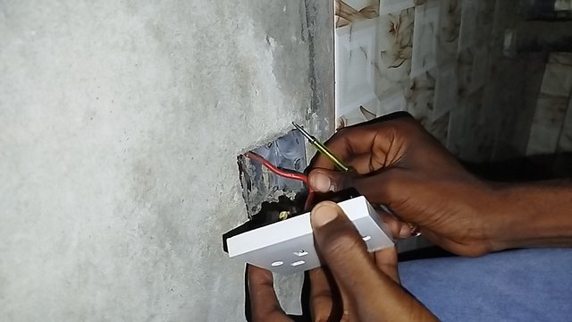
- This is my single socket, and I'll focus my attention at the back since it's where the wire would be connected. The back of the single socket has holes, and these holes are to fit in the wires. You can't just fix the wires anywhere, as there is labelling to avoid socket blows or that of devices plugged in it.
 |  |  |
|---|
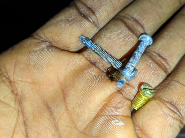
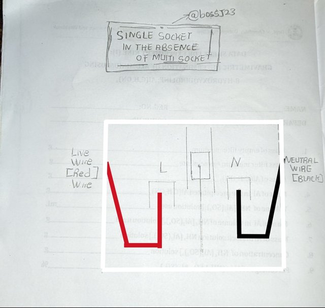
- The socket is labelled L and N, which means Live and Neutral. From my secondary school knowledge, the live wire is always the red, while the neutral wire is the black. The wires are bent in an oval shape to fit in the hole and to prevent the wire from pulling out at any instance when screwed.
- Once this was done, I placed the wires and used the knots to tighten them. It was fitted into the single socket, which I placed on the wall, screwed for use.
This is a video tutorial showing how I did it. The circuit representation diagrammatically is shown below on how the connection was possible.
Write your opinion about safety and precautions in electrical work while doing homework. |
|---|
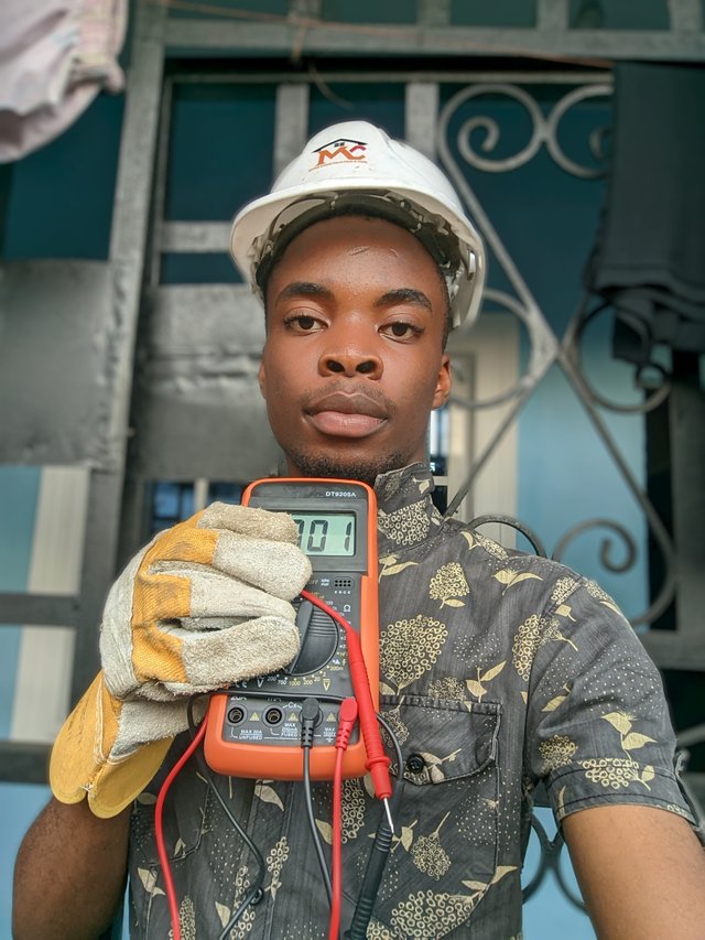
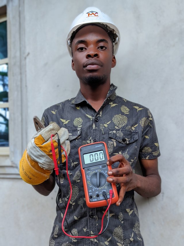
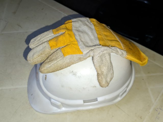
Like I said, I'm not a professional in this field. So in everything I did, I made sure I carried out safety measures by wearing personal protective equipment to prevent electric shock, which could be possible due to wrong connection or testing. I made use of
Helmet
Gloves
Shoe etc.
 |  |
|---|
My wearing a helmet in the course of carrying out this assignment is to prevent mistaken physical contact with electricity, as a part of your body can mistakenly touch something in the process. Since I was dealing with wires where current is flowing, I ensured that my gloves were on to prevent electric shock as a result of physical contact. Wearing a shoe is to prevent being thrown to the ground or compressed electrical distribution tackles the feet. I was extra careful in my doings, and with these precautions, I was able to deliver the homework successfully.
| Identification | ✅ |
|---|---|
| Neon Tester | ✅ |
| Voltage measurement | ✅ |
| Safety first | ✅ |
I invite @cletuskevin, @uduak3287 and @whizzbro4eva
Cc,
@mahadisalim
A • You present the point very well. Here you have explained the name of each tools and their function in detail. Point A will be sufficient assessment as a lesson. (2)
B • You have successfully tested your home electrical connection with a Neon tester Tester. The pictures and description you mentioned are clear to us. Nice diagram of neon tester for testing electrical activity. You got this point right. (2.5)
C • Point c you covered well. You have presented the serial connection method of electrical socket through diagram which is excellent. Also the full video of your connection procedure made it more clear. By adding video, you make your introduction more unique. (4)
D • Caution is essential in electrical work. You have taken sufficient precautions and used the tools yourself. Very nice and very carefully you have completed the whole lesson. Another safety tool you can use if you want is night vision goggles. Which will keep your eyes safe. (1.4)
Comment/Recommendation
Completed your entire post very carefully. The quality and clarity of the poster keeps the reader focused and engaged. Every point you made was very well presented. But some images are double mentioned, you can add an image from the same category if you want. Stay with our Basic Electricity Teaching Team to complete the next lessons. Take love from solaymann.
Thanks for the assessment. I really appreciate
https://x.com/bossj23Mod/status/1852257281905430767?t=43Q_Au3sReSOTB3-LXv-QQ&s=19
Dear, please submit your post link in the comments section of the lesson.
Done Sir
Thank You....
🫂
Looking at the socket outlet design which is used in your country, I noticed that different countries have different designs. I see the socket used in Nigeria looks very solid. The connections points are well placed in a safe manner.
Thanks for the comment. Most of these sockets are expensive in my area that's why I had to settle for a lower single socket. Let me check your own entry.
Appeal to community members:
Thanks for the review. Appreciated
Great post, @bossj23, bro. I appreciate the detailed analysis of electrical hand tools and measuring instruments. Your explanation about the neon tester and multimeter was especially helpful for beginners. Safety precautions are very important, and it is good to see you emphasising them. Looking forward to more informative content like this.
The Steemit team has launched Home Repair Club in Learning Challenge Session 23. (home repair items): mobile charger, power bank, USB cable & adapter, electric fan (ceiling/table fan), light (LED bulb, tube light), electric switch & multiplug, emergency light & torch, trimmer & shaving machine, hair dryer, electric kettle, rice cooker, blender & juicer. And you can share new projects.
I am @imranhassan and @rmm31 as mentors in this challenge, so I invite you to join us. I hope you will join our club and participate in the challenge.
👉 For details: Steemit Learning Clubs Season 23 | Home Repair Club Introduction and Welcome