HOW TO BUILD A 5V DC POWER SUPPLY-EXPLAINED WITH IMAGES!!
Hello Steemians I did a post last week on how to trouble shoot your car battery. you can look it up here. Today am going to be posting on how to build your own 5volt power supply.
Maybe you might have had a damaged charger and then you wished you could just build a temporary one before you are able to get a new one or maybe you are like me who loves electronics so much and then you begin to get worried that you are spending too much on batteries, don't worry because this post is going to guild you on how to build a 5volt power supply for your projects. The components needed to carry out this project are going to be as follows;
bread board
a 12v step-down transformer
7805 voltage regulator
capacitors
Diodes
In other to build this power supply we are going to follow these simple steps to build it
- Steping down the main voltage
- Rectification
- Filtration
- Steady the voltage
- Distribution
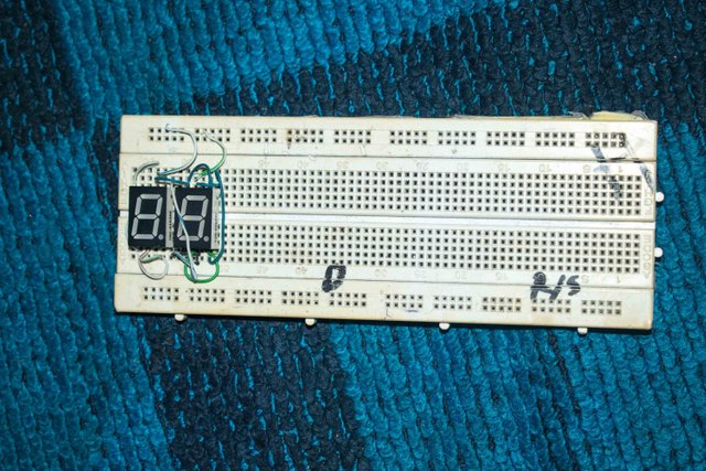
1 STEPING DOWN THE MAIN VOLTAGE.
now the voltage from the main, that is from your sockets at home is usually very high. Here in Nigeria it ranges from 220-240v and on some occasions 250v. In other to step down this voltage we are going to use a step down transformer (preferably 12v), by simply connecting the primary wire of the transformer to the main and the secondary to your bread board.
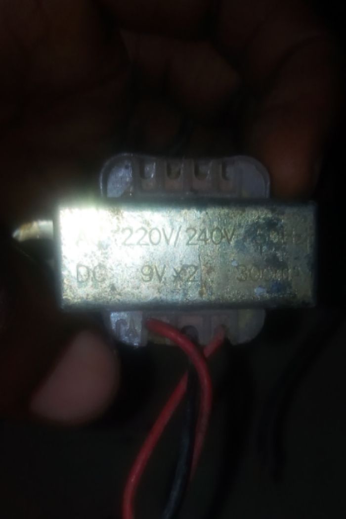
The rating of a transformer is written on top of it, like in the image below.
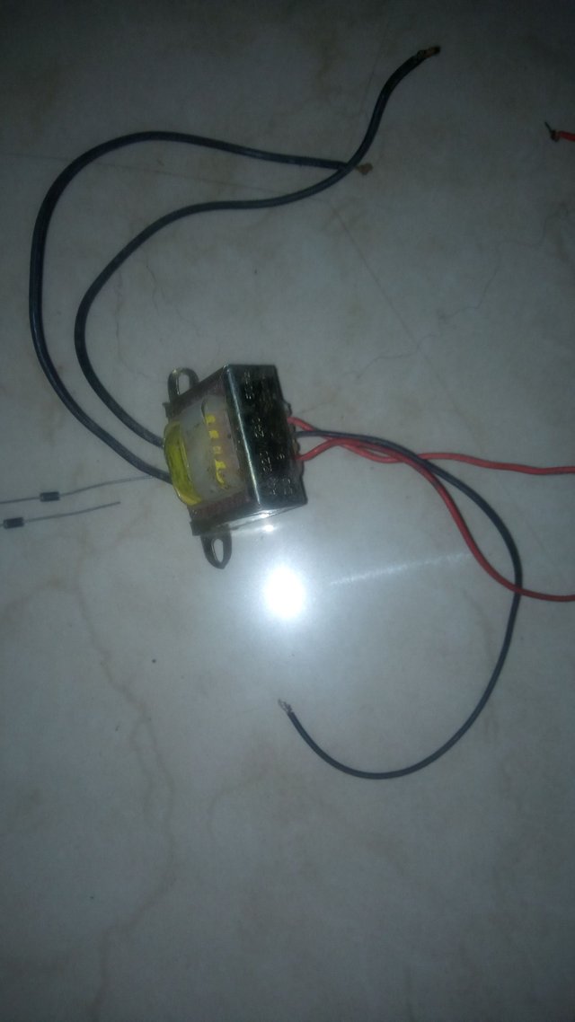
This section of the transformer is where is connected to the main (primary wire). The other section with three wire is connected to our bread board (secondary wire). In this section the middle wire is grounded.
2. RECTIFICATION
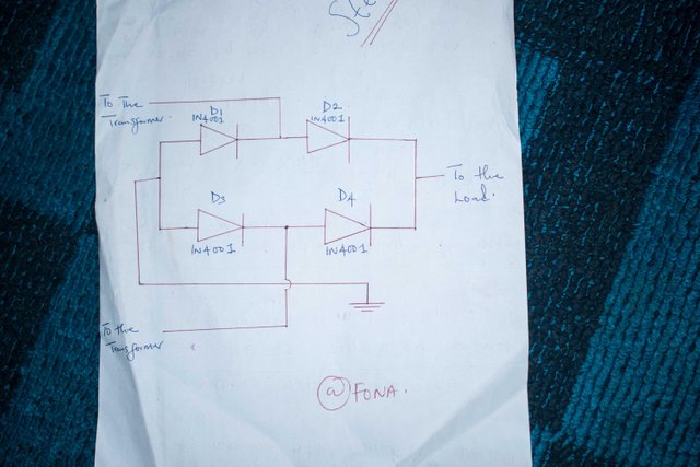
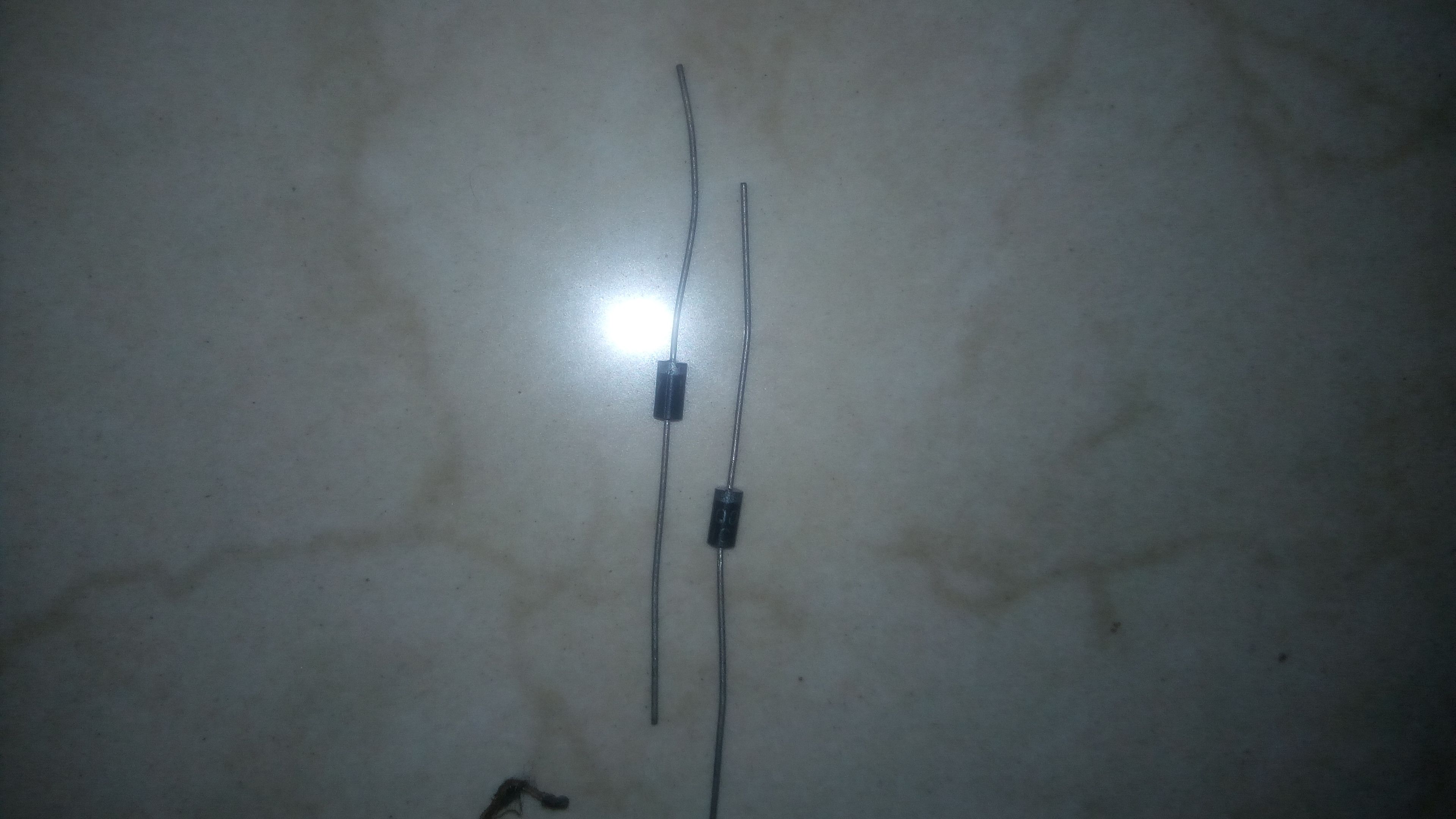
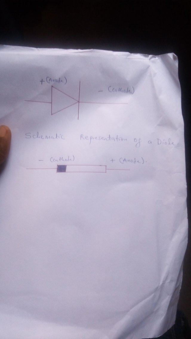
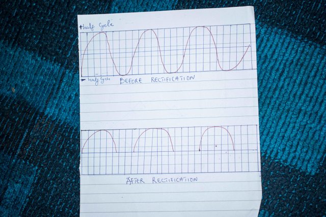
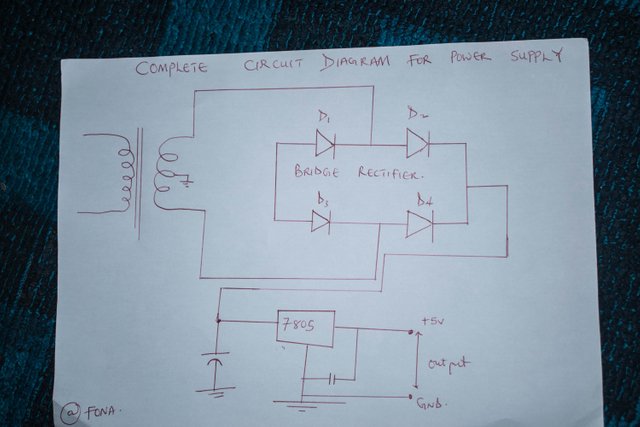
Just as it sounds, rectification is the process of converting alternating current to direct current. To carry out this process, we are going to make use of a bridge rectifier. A bridge rectifier consist of four diodes some bridge rectifiers have now been made into a single chip. Diodes are semiconductor materials that allows currently to flow only in One Direction (which is usually in the forward dirction), thereby removing the negative cycle of the alternating current, thus producing a fluctuating DC. The small silver band on the diode represent the cathode. And the large black band represent the anode.
When the positive cycle of the AC comes into the system, D1 and D2 are forward biased and D3 and D4 are reversed biased therefore current will flow only through D1 and D2. While in the negative half cycle D3 and D4 are forward biased while D1 and D2 are reversed biased, hence current flows through D3 and D4.
3. FILTRATION.
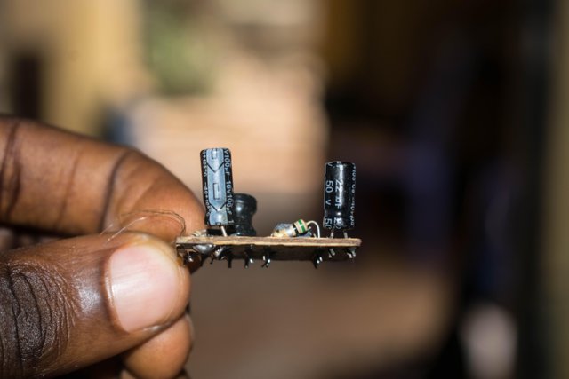
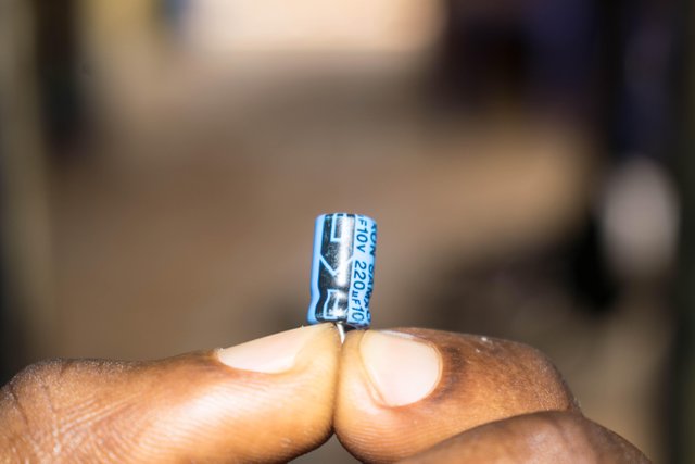
The part that is printed black is the negative pin of the capacitor.
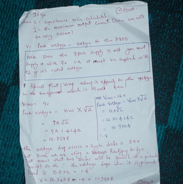
Filtration is the process of removing the ripples in the pulsating DC coming from our rectifier bridge, as the voltage from the bridge is not a pure DC. A capacitor is used to carry out this purpose. The value of the capacitor to be used is calculated using the formula C=I×(T/V) where c=capacitance I= the maximum output current. *we will make use of 500MA. T= 10ms ( here in Nigeria electricity is transferred at a frequency of 50Hz. After rectification, since the negative cycle has been removed the frequency is going to double. Therefore our frequency after rectification =2*50 =100Hz. For those outside Nigeria it's going to be the same procedure. Recall that T=1/f Where f is the frequency of ur country =1/100 =0.01 =10ms. ) V= peak voltage - voltage to the 7805 voltage regulator.
NOTE; SINCE THE 7805 GIVES AN OUTPUT OF 5V, WE MUST MAKE SURE IT IS SUPPLIED WITH +2 OF IT'S OUTPUT VOLTAGE
VRMS = 12V (if you are using a 9-0-9 1A transformer, your Vrms will be 9V.) Peak Voltage = Vrms ×√2 12×√2 = 12×1.4142 =16.9704 The voltage drop across a single diode is 0.7v, but since we are using a bridge rectifier, it means that at any time in the system two diodes are always going to be forward biased. Therefore voltage drop on the diodes =2*0.7 =1.4v Therefore V=16.9704 - 1.4 =15.5704v This is not our final V because; recall that we need to supply our 7805 voltage regulator with 7V. Therefore when our capacitor discharges, it should give 7V to the voltage regulator. Hence V=15.5704 - 7 =8.5704V. From C=I×(T/V) = 500mA ×(10ms/8.5704) =583.40uf Approximate this to 470uf. OR
for those of us who have a 9-0-9 trans former,
Peak voltage =9×√2
=9×1.4142
=12.7278v
Voltage drop across diodes =1.4 as we established above.
V=12.7278 - 1.4
=11.3278v
11.3278 - 7
Hence V=4.3278
From C=I×(T/V)
C=500mA×(10ms/4.3278)
=1154.7uf
But we don't have this kind of value for a capacitor so we approximate to 1000uf.
Hence C =1000uf.
4. STABILIZING THE VOLTAGE.
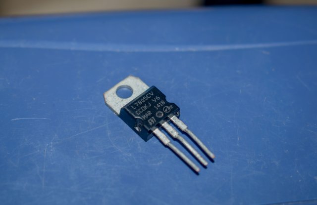
After filtration, the voltage flowing is not a steady DC, so in other to achieve this we are going to be making use of a voltage regulator (7805). There are two types of voltage regulator later;
- The fixed voltage regulator.
- The variable voltage regulator.
For this project we are going to be making use of the fixed voltage regulator which are usually the 78XX series.
where XX is the out put voltage. Ours here is 05 meaning we are going to be having an output of 5volts. In other to use the voltage regulator it is advisable to always check the data sheet.Facing the voltage regulator towards yourself like in the picture below, from the left, the first pin is the supply pin, the second is the ground pin and the third pin is the output pin (this is the pin that is connected to our load). The supply pin is usually connected to the output from the filter stage. It must always be feed with +2v of its rated output voltage. That is since the voltage regulator here gives an output of 5V, it must be supplied with 2V+5V=7V.
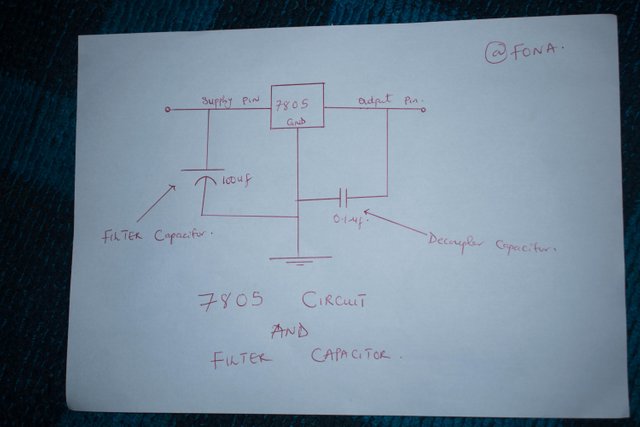
A decopler capacitor of 0.1uf should be connected from the output pin to ground so as to eliminate noise. Noise is a term used to describe the transient anges that occurs in electrical circuits. With all this our power supply is ready for use. Here are the full circuit diagram and calculations
Thanks for reading through. If you have any problems or challenge feel free to comment below.

All images in this post were taken by me with my Nikon D5300 and Tecno-L8 lite. And all the above explanations has been proven and tested by me as it pertains to my career goal as an engineer currently in my fourth year studying electrical and electronics engineering. Till my next post I remain your real-G @fona.
Dude totally love your post. Im new to this electronic field. This article is so useful for all electronic newbie out there. Cause i believe every tinkerer must start with building your own power supply. Its the most basic. Great jib with your explanations. I do hope more such post from you.
I really agree with you a power supply is very crucial for any electronics Project. You're going to definitely see more post from me on electronics
Great! Are you an engineer? Or just a hobbyist?
I would love say both, but am still in school studying electrical and electronics engineering
Ahh I have so many things I wanted to fix. I just hot air reworked an onboard lan chip. BUt i can't figure out what's wrong as there's no led light for gigabit connection. That's my dilemma for now haha.
You can try using your multimeter to check for voltage drop on each component since there is no led indicator
@fona, you did a nice post.
So explanatory, i got something from that.
Am glad you gained from it @hboi
Wow! You did a really nice job @fona. Nice pictures btw.
Thank you @jaff8
Awesome!
Thank you @pangoli
Nice one, i really enjoyed your article
Am glad you enjoyed it @druids
Oga fona!!
Nice work
Thank you @ced000
This post was promoted with @monitorcap traffic bot & STEEM promotion service.
Send MIN. $1 SBD to @monitorcap bot with your link in MEMO field
and recieve upvotes & resteems for your posts. @monitorcap - where 'seen' matters !