THEVENIN THEOREM - THEORETICAL FUNDAMENTALS
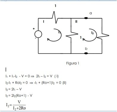
Consider that there is a resistive network of independent sources as shown in Figure 1 in which resistor Ro is connected at nodes a and b. Assume also that it is desired to calculate the current through the resistor for any value of the specified resistance.
This equation provides a solution for the current through the resistor Ro for any resistance value. Now consider a second procedure to solve this circuit. Connect a resistor Ro to the nodes c and d of a circuit formed by a single voltage source with a value of V / 2 and a resistor with a value equal to ½ ohm, as shown in figure 2.
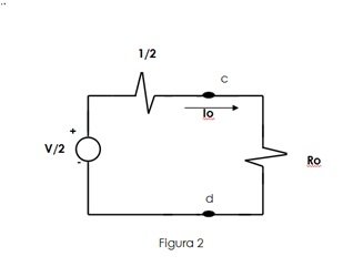
Applying the law of voltages of Kirchhoff it is obtained that:
Io(1/2) + IoRo = V/2

When comparing these last two equations it is observed that, for a given expression of v, the same current will flow through the resistor Ro, whether connected to the nodes a and b of the circuit shown in Fig. 1 (in this case, the current is I2). ), or to the nodes c and d of the circuit of Fig. 2 (in this case the current is Io). In addition this statement is valid for any Ro. So we can say that the two circuits (not including Ro) that appear in the two figures are equivalent with respect to their behavior in the pair of nodes indicated. The circuit shown in Figure 2, consisting of a single voltage source in series with a single resistor is called Thevenin equivalent of the resistive network (not including Ro) shown in Figure 1. Said equivalent circuit can be obtained for any network composed of linear resistors and independent sources.
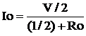
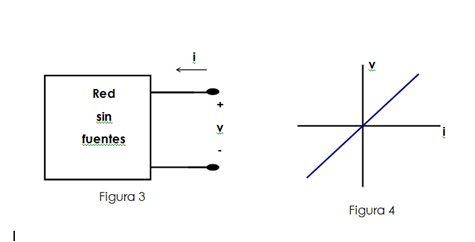
Consider the properties that such an arbitrary network should have if all of its internal sources are set to zero, that is, if all current sources are replaced by open circuits and all voltage sources are replaced by short circuits. Since the resulting network (without sources) contains only resistors, there is the possibility that a specific pair of nodes is replaced by a single resistor, whose value is the input resistance of the network seen in that pair of nodes. Therefore, if we define the variables v (t) and i (t) in the terminals of said network without sources, as illustrated in Figure 3, the input characteristics must be represented by the straight line passing through the origin of a plane iv, as shown in figure 4. The slope of this line is proportional to the value of the input resistance.
In general, a voltage will be present between its terminals, due to the effects of the sources, even when no current flows in the terminals. If a current is also applied to the terminals of the network (by means of an external current source), then, due to the linearity of the resistive network, this source must produce the same effect as when it was used to excite the network without sources. However, in this case it is superimposed on the effect of the internal sources of the network. The additional effect is determined by the value of the equivalent resistance of the network, that is, by the slope of the characteristic i-v. In this way, we observe that the original network must have a complete feature, consisting of a line straight on the i-v plane that does not pass through the origin as illustrated in figure 5.
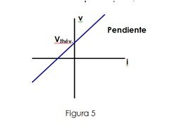
This representation is equivalent to that of an ideal voltage source in series with a linear resistor. In this way it is concluded that an original network can be replaced by an equivalent circuit consisting of a voltage source in series with a single resistor. This statement is summarized in the statement of Thevenin's theorem, so named, in honor of the French telegraph engineer Charles Leon Thevenin (1857-1926), who published his results in 1883 and which states the following:
"Any network composed of linear resistors and independent sources can be replaced by an equivalent circuit consisting of a single voltage source and a single resistor in series", as shown in Figure No. 6.
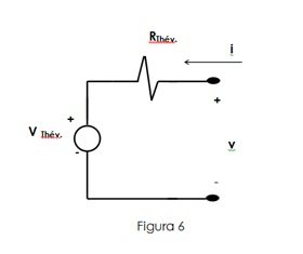
Such a circuit is called the Thevenin equivalent circuit. The value of the resistor corresponds to the input resistance seen in the pair of nodes when all independent sources of the original network are set to zero. The value of the source is that observed in the terminals in open circuit.
Thank you for visiting my blog
Eng. Rance Zambrano