Solidworks 101 #3- The Solidworks User Interface
Good day steemians, @jamesanity06 here back with another part of our tutorial-ish blog about Solidworks, in this episode, we will discuss about the Solidworks User Interface. I'll give an in-depth guide on Solidworks User Interface and some extra tips for y'all who're reading and following this blog. So, without further ado, let's proceed with the blog, shall we?
The Solidworks User Interface
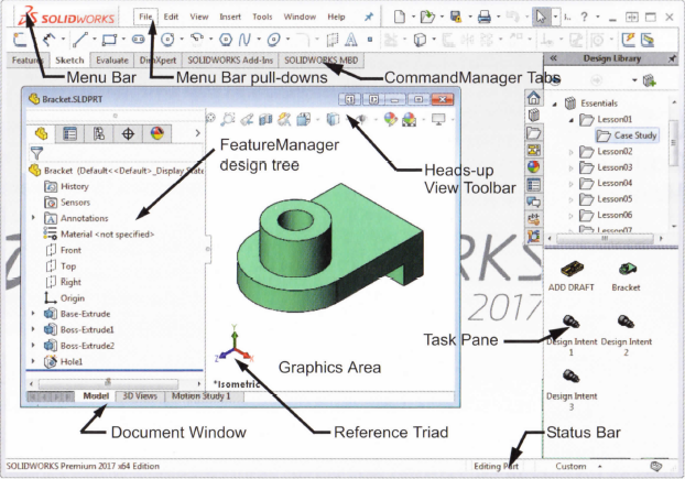
The _**Solidworks user interface is a native Windows interface, and as such, behaves in the same manner as other Windows applications. Some of the more important aspects of the interface are identified below.
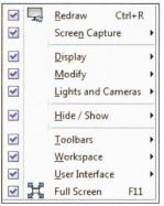
Pull-down Menus
The pull-down menus provide access to many of the commands that the Solidworks software offers. Float over the right facing arrow to access the menus. Click the puchpin to keep the menus open.

When a menu item has a right-pointing arrow, it means that there is a sub-menu associated with that choice.
When a menu item is followed by ellipses, it means that the option opens a dialog box with additional choices or information.
Customizing the Pull-down Menus
When the "Customize menu item is selected, each item appears with a check box, Clearing the check box removes the associated item from the menu.Using the Command Manager
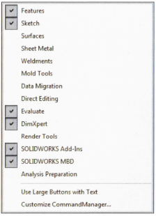
The CommandManager is a set of icons divided into tabs that are geared towards specific tasks. For example, the part version has several tabs to access, commands related to features, sketches, and so on.

Note: The CommandManager can be displayed with or without text on the buttons. These images show the "Use Large Buttons with text" option.
Adding and Removing CommandManager Tabs
The default settings show five CommandManager tabs for a part file. Other can be added or removed by right-clicking on any tab and clicking or clearing the tab by name.There are different sets of tabs for part assembly and drawing files.
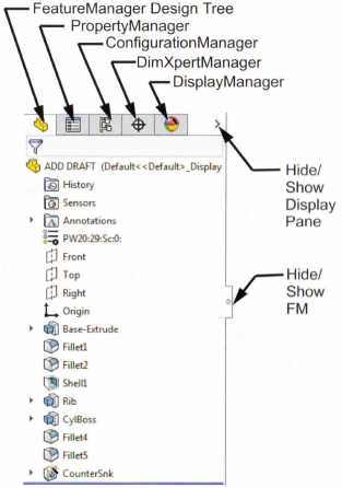
Featuremanager Design Tree
The FeatureManager design tree is a unique part of the "Solidworks" software that visually displays all the features in a part or assembly. As features are created, they are added to the FeatureManager design tree. As a result, the FeatureManager design tree represents the chronological sequence of modeling operations. The FeatureManager design tree also allows access to the editing of features (objects) that it contains.Show and Hide FeatureManager Items
Many FeatureManager items (icons and folders) are hidden by default. In the image above, only two folders (Sensors and Annotations) are shown (the History folder can't be displayed or hidden, since it's a fixed folder in FeatureManager).
Click Tools>Options>System Options and FeatureManager to control their visibility using one of the three settings explained below the image reference.
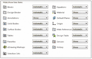
• Automatic - Hide the item when it is empty.
• Hide - Hide the item at all times.
• Show - Show the item at all times.
PropertyManager
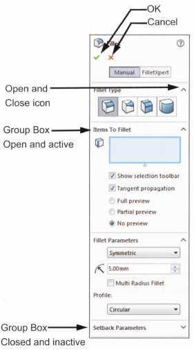
many Solidworks commands are executed through the PropertyManager. The PropertyManager occupies the same screen positions as the FeatureManager design tree and replaces it when it is in use.
The top row buttons contain the standard OK and Cancel buttons.
Below the top row of buttons are one or more "Group Boxes" that contain related options. They can be opened (expanded) or closed (collapsed) and in many cases made active or inactive.Full path name
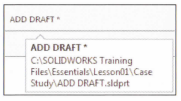
The full path name of the document can be seen as a tool tip when floating or hovering the cursor over the file name.Selection Breadcrumbs
Selection Breadcrumbs show the hierarchy of objects based on a selected piece of geometry. For example, selecting a face can lead to a series of objects including the feature, solid body, component sub-assembly,and finally to the top level assembly.It also leads to the sketch of the feature and the mates attached to that component.
These visual objects can also be used for access. Right-clicking on the boss feature offers several editing tools including Edit Feature and Hide.
Note: These objects and tools will be discussed later on so you better follow me and stay tuned. XD
Task Pane
The Task Pane window contains the Solidworks Forum, Solidworks Resources, Design Library, File Explorer View Palette, Appearances, Scenes, Decals and Custom Properties options. The window appears on the right but it can be moved and resized. It can be opened/closed, tacked or moved from its default position on the right side of the interface.
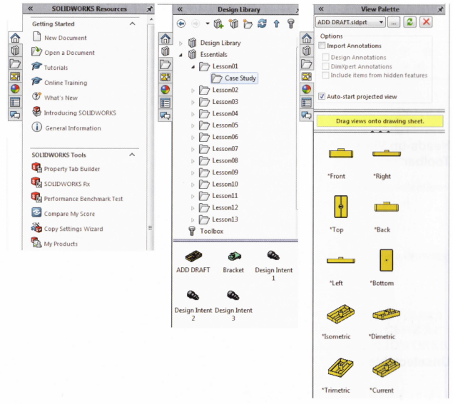
Opening Labs with the File Explorer
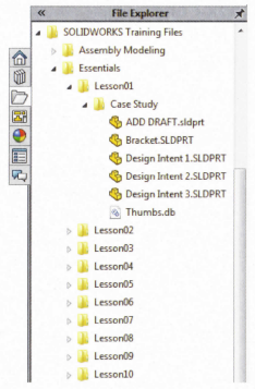
You can open parts and assemblies required for lab excersices using the File Explorer• Open the "Task Pane".
• Click "File Explorer".
• Expand the "Essentials" folder used for the class files. It should be found under the "Solidworks Training" folder.
• Double-click a part or assembly file to open it.
Heads-up View Toolbar
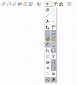
The "Heads-up View" toolbar is a transparent toolbar that contains many common view manipulation commands. Many of the icons (such as the "Hide/Show Items) are "Flyout Tool" buttons that contain a small down arrow to access the other commands.Unselectable Icons
At times you will notice commands, icons, and menu options that are grayed out and unselectable. this is because you may not be working in the proper environment to access those options. For example, if you are working in a sketch (Edit Sketch mode), you have full access to all the sketch tools. However, you cannot select the icons such as fillet or chamfer on the Features tab of the CommandManager. This design helps the inexperienced user (like me!) by limiting the choices to only those that are appropriate.
To Preselect or Not?
As a rule, the Solidworks software does not require you to preselect objects before opening a menu or dialog box. For example, if you want to add some fillets to the edges of your model, you have complete freedom, you can select the edges first then click the Fillet tool or you can click the *Fillet tool then select the edges. The choice is yours!
Mouse Buttons
The left, right and middle mouse buttons have distinct meanings in Solidworks.
• Left - Select the object such as geometry, menus buttons, and objects in the FeatureManager design tree.
• Right - Activates a context sensitive shortcut menu,. The contents of the menu differ depending on what object the cursor is hovering over. These menus also represent shortcuts to frequently used commands.
• Middle or the Mouse Wheel Button - dynamically rotates, pans or zooms a part or assembly. Pans a drawing.
Shortcut menu
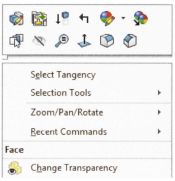
At the top of the "Shortcut Menu" is the "Context Toolbar". It contains some of the most commonly used commands in icon form.Below it is the pull-down menu. It contains other commands that are available in the context of the selection, in this example a face.
Note: The context toolbar will also become available as you make selections with the left mouse button. It provides quick access to common commands.
Keyboard Shortcuts
Solidworks conforms to standard Windows conventions for such shortcuts as Ctrl+O for File>Open; Ctrl+S for File>Save; Ctrl+Z for Edit>Undo and so on. In addition, you can customize Solidworks by creating your own shortcuts.
Multiple Monitor Displays
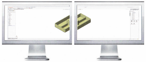
Solidworks can take advantage of multiple monitor display to span monitors and to move document windows or menus to a different monitors.
Spanning Monitors
Click Span Displays on the top bar of the Solidworks window to stretch the display across both monitors, just like shown in the image below.
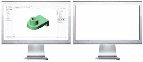
Fitting to a Monitor
Click either Click to Tile Left or Click to Tile Right on the top bar of a document to fit it to the left or right monitor.
System Feedback
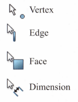
Feedback is provided by a symbol attached to the cursor arrow, indicating what you are selecting or what the system is expecting you to select. As the cursor floats across the model, feedback will come in the form of symbols, riding next to the cursor. The illustration at the right shows some of the symbols: vertex, edge, face and dimension.Options
Located on the Tools menu, the Options dialog box enables you to customize the Solidworks software to reflect such things as your company's drafting standards as well as your individual preferences and work environment.
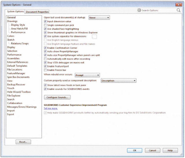
Tip: Use the search bar in the upper right of the "Options" dialog box to find system options and document properties. Type the label of the check box, radio button or other option to locate the page where the option resides.
Customization
You have several levels of customization. They are:
• System Options - The options grouped under the System Options are saved on your system and affect every document you open in your _Solidworks*_ session. System settings allow you to control and customize your work environment. For example, you might like working with colored viewpoint. The same files opened on other system would not.
• Document Properties - These settings are applied to the individual document. For example, units, drafting standards, and material properties (density) are all document settings. They are saved with the document and do not change regardless of whose system the document is opened on.
• Document Templates - Document templates are pre-defined documents that were set up with certain specific settings. For example, you might want two different templates for parts. One with English settings such as ANSI drafting standards and inch units, and one with metric settings such as millimeters units and ISO drafting standards. You can set up as many different document templates as you need. They can be organized into different folders for easy access when opening new documents. you can create document templates for parts, assemblies, and drawings.
• Object - Many times the properties of an individual object can be changed or edited. For example, you can change the default display of a dimension to suppress one or both extension lines, or you can change the color of a feature.
Search
The Search option can be used to find information from Solidworks Help, Commands, Files and Models on your system by searching for any part of the name (*requires Windows Desktop Search engine).
Disclaimer: All images are provided using actual screen shots of the software and some photo editing.
So this sums up our discussion, and tutorial-ish for the 3rd installment of our little Solidworks blog, please follow me @jamesanity06, and stay tuned for more of our Solidworks tuts. Thank you for reading, and have a good day! James is bouncing off the building!
© @jamesanity06, 2018

Damo nga Salamat! Maraming Salamat po! Thank you Very Much!

I am a part of @steemitfamilyph. Join us! Follow - Upvote - Resteem - Comment
Be a member of our Facebook page -- Join Us Here
© @jamesanity06, 2018

Damo nga Salamat! Maraming Salamat po! Thank you Very Much!

I am a part of @steemitfamilyph. Join us! Follow - Upvote - Resteem - Comment
Be a member of our Facebook page -- Join Us Here
