Solidworks 101 - #2 - Design Intent and A few Add-Ons
This is a continuation of my Solidworks tutorial-ish blog. And today I will discuss about Design Intent and a few add-ons. So sit tight, relax and enjoy this little tutorial-ish for those who are interested in learning how to use Solidworks (basic usage only ofc!).
Design Intent
In order to use a parametric modeler like SolidWorks efficiently, you must consider the design intent before modeling. Design intent is your plan as to how the model should behave when it is changed. The Several factors contribute to how you capture design intent:
•Automatic (Sketch) Relations
Based on how geometry is sketched, these relations can provide common geometric relationships between objects such as parallel, perpendicular, horizontal, and vertical.
•Equations
Used to relate dimensions algebraically, they provide an external way of force changes.
•Added Relations
Added to the model as it is created, relations provide another way to connect related geometry. Some common relations are concentric, tangent, coincident, and collinear.
•Dimensioning
Consider your design intent when applying dimensions to a sketch. What are the dimensions that drive the design? What values are known> Which are important for the production of the model? The way dimensions are applied to the model will determine how the geometry will change if modifications are made.
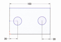
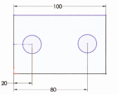
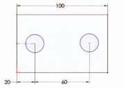
Consider the design intent in the following examples.
Examples of Design Intent
The design intent of each sketch below is slightly different. how will the geometry be affected if the overall plate width, 100mm is changed?
How Features Affect Design Intent
The "Layer Cake" Approach
The layer cake approach build the part once piece at a time, adding each layer, or feature, onto the previous one, like this:

Changing the thickness of one layer has a ripple effect, changing the position of the other layers that were created after it.
The "Potter's Wheel" Approach

The Manufacturing Approach
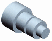
The manufacturing approach to modeling mimics the way the part would be manufactured. For example, if this stepped shaft was turned on a "lathe" machine, you would start with a piece of bar stock and remove material using a series of cuts.

There is not really a right or wrong answer when trying to determine which approach to use. Solidworks allows for great flexibility and making changes to models is relatively easy. But creating models with design intent in mind will result in well built documents that are easily modifiable and well suited for re-use, making your job easier.
That's it for the Design Intent part, let's take a breather for now and digest what we have discussed. And while we're at it, I'll throw in some add-ons as a bonus
Object Linking and Embedding (OLE)
In the Windows environment, information sharing between files can be handles either by linking or embedding the information.
The main difference between linked objects and embedded objects are where the data is stored and how you update the data after you place it in the destination file.
•Linked Objects
When an object is linked, information is updated only if the source file is modified. Linked data is stored in the source file. The destination file stores only the location of the source file (an external reference), and it displays a representation of the linked data.
Linking is also useful when you want to include information that is maintained independently, such as data collected by a different department.
•Embedded Objects
When you embed an object, information in the destination file doesn't change if you modify the source file. Embedded objects become part of the destination file and, once inserted, are no longer part of the source file.
In the previous lesson, we talked about File Reference, in this lesson, I will be giving a little graphic presentation about File Rreference.
File Reference Example and Diagram
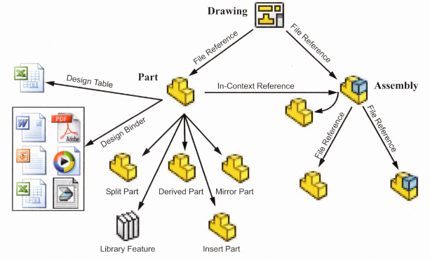
The different types of external references created by Solidworks are shown in the following graphic. Some of the references can be linked or embedded.
That's it folks for the second part of our Solidworks tutorial-ish* session. Follow me and stay tuned for more Solidworks tutorials. Thanks for reading and have a good day! @jamesanity's bouncing off the building!!
© @jamesanity06, 2018

Damo nga Salamat! Maraming Salamat po! Thank you Very Much!

I am a part of @steemitfamilyph. Join us! Follow - Upvote - Resteem - Comment
Be a member on our Facebook page -- Click this Link