RC Snubber Explained
Introduction
The simple capacitor-resistor snubber circuit consists of a resistor and a capacitor that are joined in series. The resistor assists in absorbing the energy of voltage fluctuations, and the capacitor serves as a short-term store for the energy. Thus, the possibility of a sudden shift in the electrical flow damage is minimized.
Why is an RC Snubber Needed?
A voltage spike occurs when the power source experiences an occasional increase in the voltage. The issue with voltage surges as well as electricity is they can cause your electronic devices to fail or malfunction without you being aware initially. This can include your refrigerator, stove television, computer, and many more. The RC snubbers must be used since they protect you from sudden fluctuations in voltage. They convert the energy into heat energy, rather than causing issues like voltage surges or melting circuits. The RC snubbers are simple to install and can be mounted on your electronic devices. Additionally, they can help reduce the EMI noise and improve the reliability of your circuit.

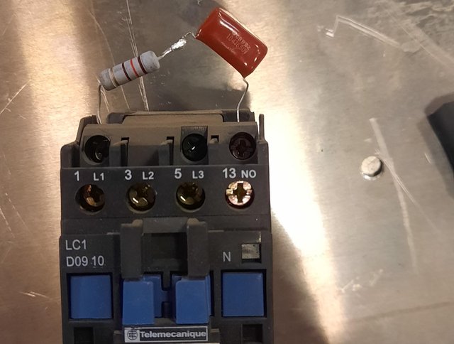
(RC snubber attached to the coil terminal to "snub" the current spikes)
RC Snubber Circuit Working Principle
The idea that drives the operation of an RC snubber circuit can be described as simple. A fluctuating voltage or current gets through a wire connecting to an electronic component. it could likely harm the circuit inside. An RC snubber circuit reduces the current and therefore stops any harm.
A relay or SCR controller is a way to alter the resistance of this circuit to limit the flow of electricity through it. As the voltage rises its resistance decreases and is reversed. The capacitors in parallel are activated when voltage increases and can hold more energy. This means that the resistance of resistors decreases and consequently the circuits' current will decrease.
So the electric capacitor can be utilized to limit or absorb abrupt increases in voltage. The role that a resistor serves is to disperse or reduce the magnetic flux energy through this process to ensure that there are no injuries.
How to Design an RC Snubber
It is the first thing to establish how much the switching voltage is. It is important to determine the maximum rating for current. must be taken into account as should the minimum rating for the resistor. Consider the frequency at which the switch would be in this particular circuit. Then, consider the dimension of the capacitor you'd like to use for your snubber circuit.
If you've decided on what frequency to use then you need to find out what the voltage of RMS is. This can be done either such as by calculating it or using graphs. After the RMS rating is determined it will inform you of the amount of current going to traverse your circuit. It is the next thing to do to calculate the duration of the circuit which is the opposite of frequency. Then, divide this by the RMS value of the voltage.

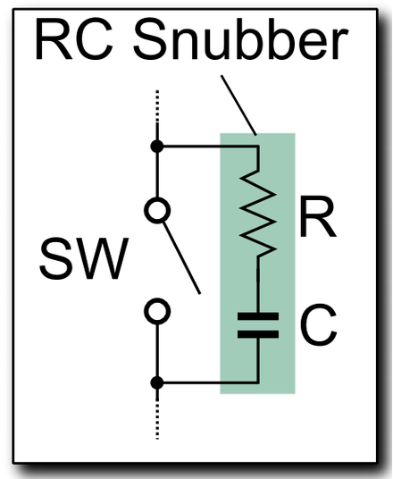
(Typical diagram that shows one RC snubber)
Resistor Selection
Another method of determining the resistor you require is choosing the span. This is the process of deciding the distance from the maximal current capacity you wish to reach when it is zero amps. Then, you can decide the minimum current that your system. The equation for the resistor's value can be calculated using the method of multiplying the intended length by 0.732 and this should be a number that, when multiplied by the maximum current rating, equals or exceeds the voltage of your RMS. When you've determined the resistance value that works best for your particular circuit It is strongly recommended to not exceed the limit of this value.
Capacitor Selection
Then, you must decide on the appropriate size capacitor to provide the right amount of current to your circuit. Three formulas are available however they all begin with determining what capacitance is required to cut the voltage of the resistor by about half. Once you have this information then determine the ripple voltage that will add to the final before you select a capacitor that can be able to handle the ripple voltage.
Notes for Applying RC Snubber Circuits
1. By the RC snubber diagram The dissipation of the resistance must be spotted and dealt with appropriately to ensure an acceptable degree of heat. This equation can be used to calculate the equation:
Loss=CxVIN2xFSW
In this case, C = Capacitance, and In is the voltage, In=Supply Voltage, and F SW=the frequency of the switch.
2. If a snubber circuit is utilized it will reduce efficiency when the transition from one state to the next occurs more slowly. This is why the level of noise as well as energy efficiency has to be considered.
Summary
In short this way, in essence, the RC snubber is a type of circuit that snuffs out voltage spikes and keeps them from causing damage to equipment or circuits. This inverter circuit example illustrates an easy RC snubber circuit. It is possible to configure the snubber circuit in a variety of ways to meet your specific needs.