Hello Steemians !
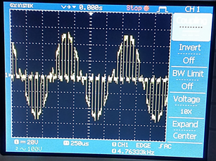 This is an output of a Pulse Amplitude Modulation shown in oscilloscope.
But first let us define PAM :)
Pulse-amplitude modulation (PAM) is a form of signal modulation where the message information is encoded in the amplitude of a series of signal pulses. It is an analog pulse modulation scheme in which the amplitudes of a train of carrier pulses are varied according to the sample value of the message signal. Demodulation is performed by detecting the amplitude level of the carrier at every single period.
On this project, we had able to use the following materials and equipment:
- 1 piece of 2N3904 transistor
- 4 pieces of 10kΩ resistor
- 2 pieces of 0.01µF capacitor
- 2 function generators ( pulse and sine is to be set)
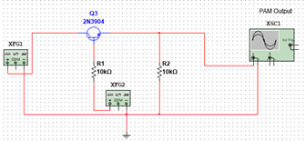 The figure above is the schematic diagram of PAM. It is simulated using Multisim. It should be followed in order to achieve good quality of PAM
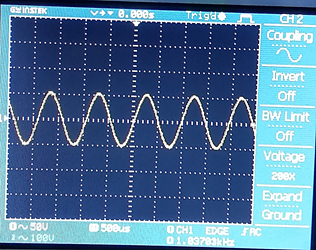 The picture above is the input sine signal or XFG1 in the shcematic.
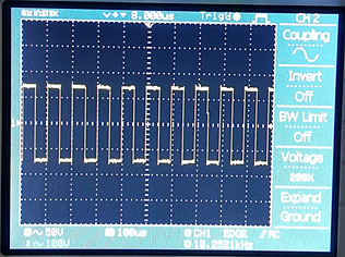 Input pulse signal or XFG2
If you try to follow the circuit, you can have your own PAM circuit and Ouput :)
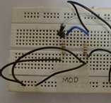 By the way, this is the actual project of Pulse Amplitude Modulation


