Replacing the fan from my lab bench power supply
As a hobby "electrician" it is kind of necessary to have a lab bench power supply.
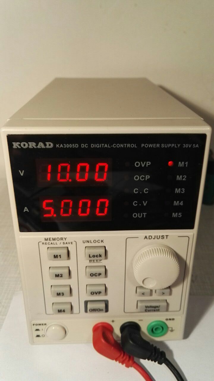
I got the KORAD KA3005D power supply and I am using it for around one year without any problems exept the fan...
Some features about it:
- voltage range from 0 to 30 Volts
- current range from 0 to 5 Amps
- Constant Current
- Constant Voltage
- 5 voltage/current save states (M1-5)
- Over current/voltage protection
The reason why I changed the fan is that the standard build-in fan makes weird noises. So lets get started! :D
Remove the case
There are some screws that need to be unscrewed.
In the back there is the fan I want to remove. But it is attached to a heatsink and a pcb...
Preparation
I have removed the zip ties that are holding some wires in place. So I have more room to move parts around.
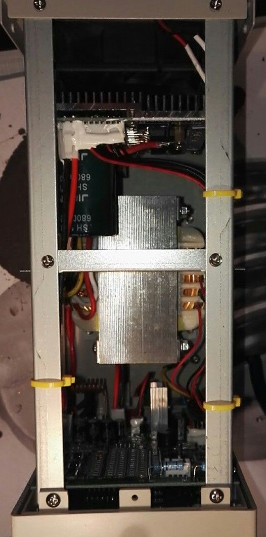
Also I removed the plate in the middle, secured with two screws.
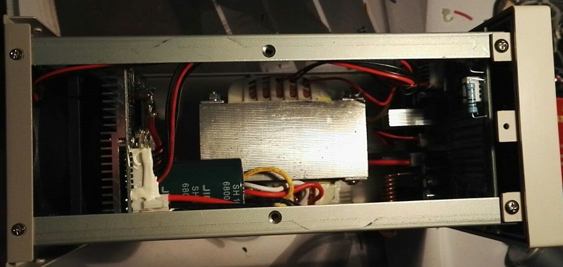
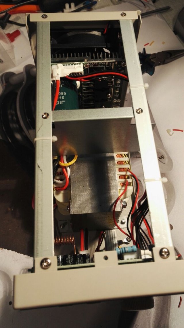
Here is how it should like now:
Remove the fan
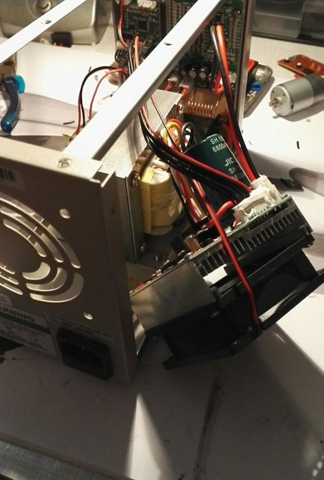
At the back of the power supply there are four screws holding the fan in place. I removed them and then gently pulled the fan, heatsink and pcb package out of the case.
Thats how it looked like:
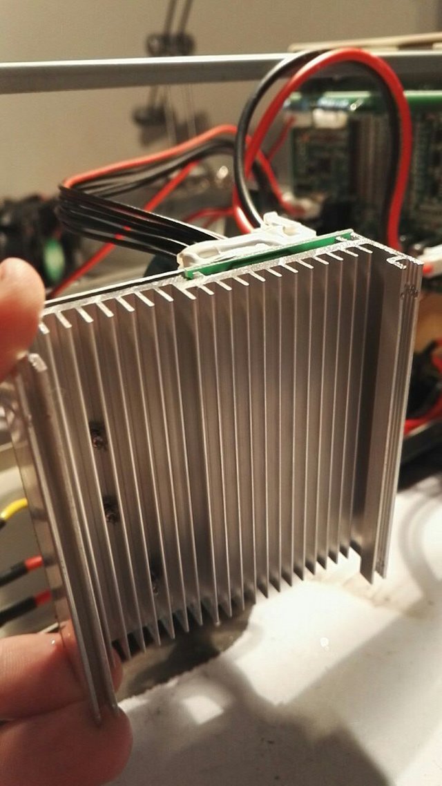
To get the fan out of this package, I removed the four screws which can be accessed trough the holes in the corners of the fan.
After that I simply cut the wire which is connected to the fan with a wirecutter...
Prepare the "new" fan and the wires from the power suppy
As a repacement I used a fan I got from an old ATX power supply.
I removed the isolation from the red and black wire and tinned it with my soldering iron.
After that I pulled around 2 centimeters of shrinking tube over each wire.
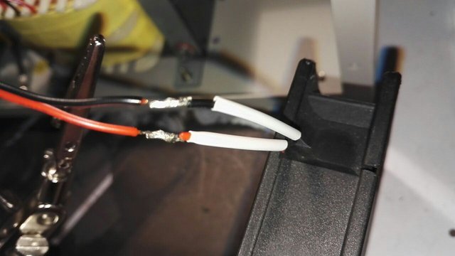
I also removed the isolation from both wires that are connected to the power supply and tinned them too.
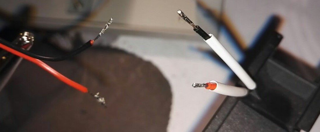
Here there are side by side with the shrinking tube
Solder them together
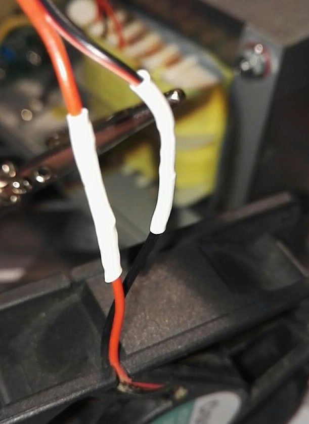
After soldering the wires together I pulled the shrinking tube over the solder joint and heated it gently.
Put everything together
I mounted the fan back to the heatsink. The heatsink has four holes at the corners just align them with the holes in the fan.
Make sure the fan is pointing in the direction the build-in fan was pointing to!
After that I inserted the fan, heatsink and pcb package back in the case and secured it with the four screws in the back.
Tidy up the wires
I used yellow zip ties which I positioned like the original ones. In addition I mounted the plate back in the middle of the case.
Close the case
Yeah thats it... :D
Now I got a more silent power supply!
!!Attention!!
Make sure that the case is properly connected to ground to avoid an electrical shock!
The case itself is coated -> not conductive
BUT the screws are!
Last words
There aren't that many pictures about each step if you have any questions about a specific step or if there is something not understandable please ask!
I hope you liked the little project!
Join our Discord Channel to connect with us and nominate your own or somebody else's posts in our review channel.
Help us to reward you for making it ! Join our voting trail or delegate steem power to the community account.
Your post is also presented on the community website www.steemmakers.com where you can find other selected content.
If you like our work, please consider upvoting this comment to support the growth of our community. Thank you.