DIY "SMART" 6X USB CHARGER
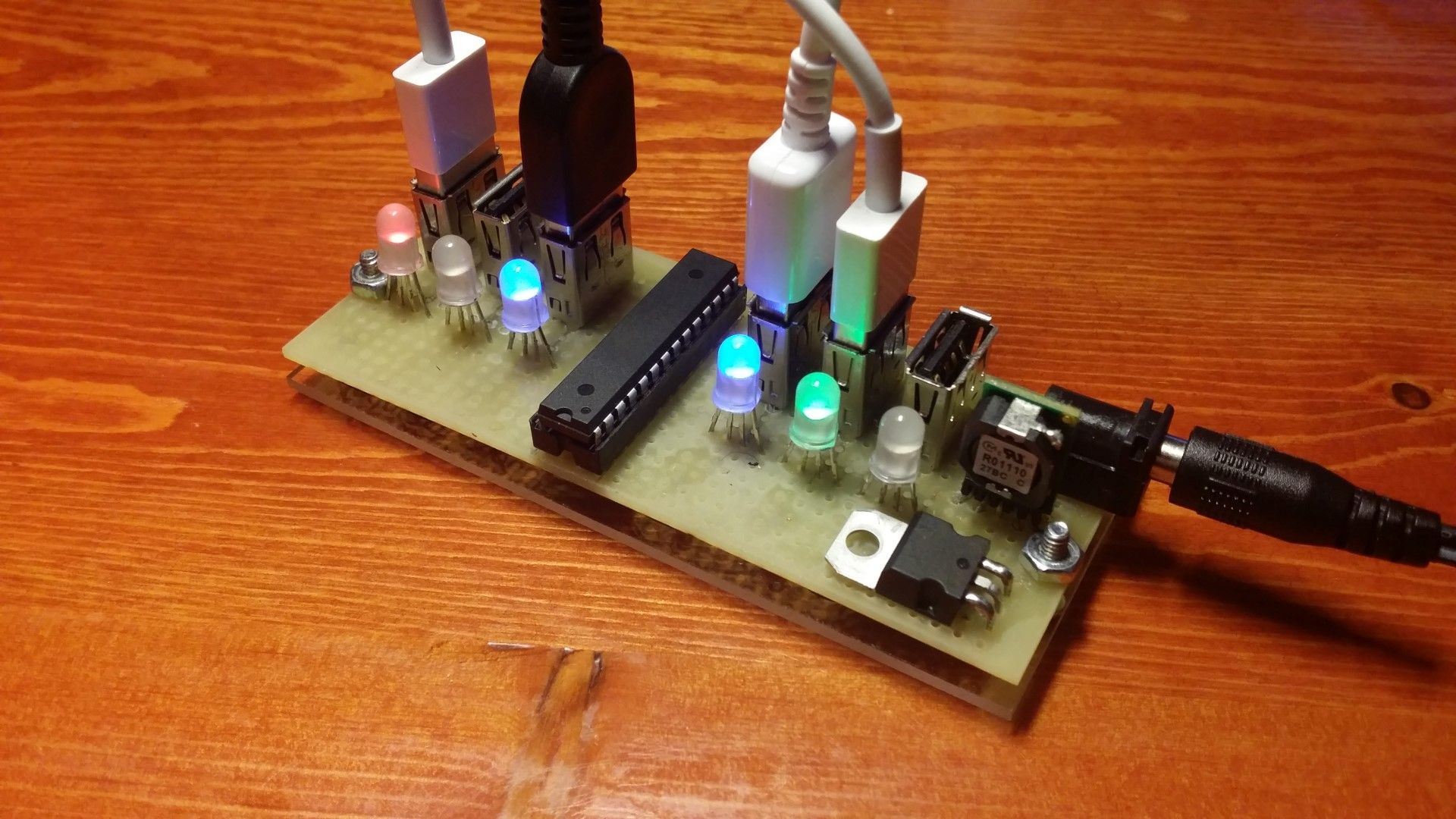
This is a simple 6 port USB device charger with a individual current monitor on each port. The charging current is indicated using RGB LEDs. Blue means slow charge (under 250mA), green means 250mA to 750mA, red means over 750mA, and purple means over 1500mA (for tablets). This circuit involves an ATmega328P (IC SOCKET), INA169 , and a OKR-T10-W12.
While this project is not as impressive as other projects i did in terms of difficulty, which i will be posting soon, I soldered and programmed this entire project in just one day with mostly spare parts and no pre-planning. I hope to inspire you to solve everyday problems by DIY instead of buying stuff!!
The problem I faced was that I had too many devices to recharge at once, not having enough chargers and not having enough AC jacks. Also my new Sony wireless headset was being picky about both the cable I use and the charger I use. I decided to troubleshoot this problem by building this tool.
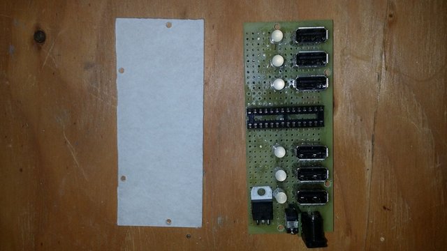
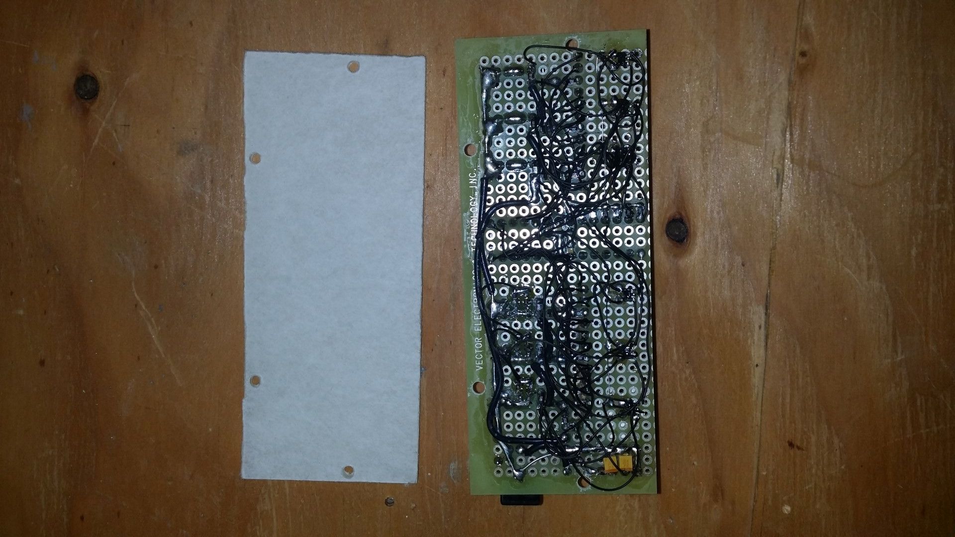
Construction is mainly done on perfboard, using through hole components mostly (where I must or where I need mechanical strength), mixed with surface mounted components whenever possible (0603, 0805, and SOT-23-5). Wiring is done using 30 gauge Kynar coated wire, with thicker wiring where high current is needed. A decently capable wall-wart is needed, anywhere between 4.5V to 12V is acceptable, and it must be able to supply enough current for all the devices to be charged. A DC/DC converter is used to increase efficiency, so a 12V wall-wart supplying 4A can actually charge about 8A total. A piece of acrylic plastic on the bottom prevents the wiring from being damaged when the circuit is sitting on a desk or being handled. The D+ and D- signals have the appropriate resistors to enable high charging rates on Apple devices (which is also compatible with Sony, Samsung, and other brands).
Extra features I did not want to include: reverse polarity protection, input fuse, individual over-current cutoff, LED dimming, etc. I know some people might suggest these to me, I am aware of these possible features but I didn’t want to include them due to cost and time and convenience.
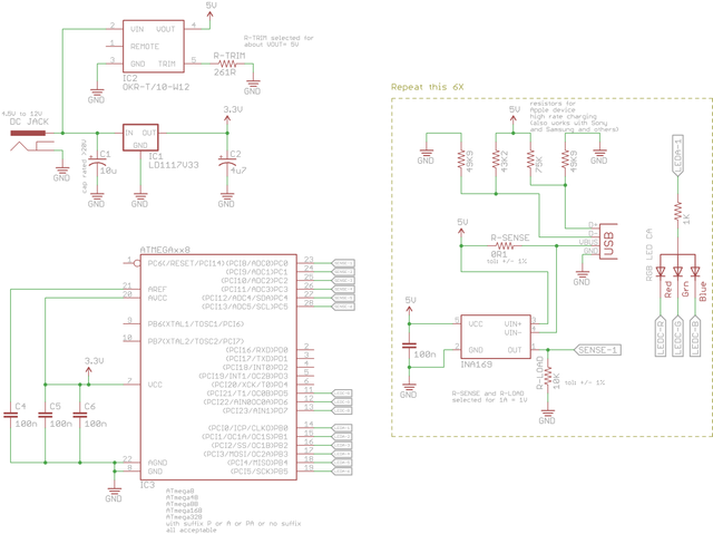
Here is the schematic and firmware C code
#include <avr/io.h>
#define THRESHOLD_HYSTERISIS 1
#define THRESHOLD_MIN 1
#define THRESHOLD_25MA 2
#define THRESHOLD_50MA 4
#define THRESHOLD_250MA 19
#define THRESHOLD_500MA 39
#define THRESHOLD_750MA 58
#define THRESHOLD_1500MA 116
#define LED_COMMON_PORTx PORTB
#define LED_COMMON_DDRx DDRB
#define LED_COLOUR_PORTx PORTD
#define LED_COLOUR_DDRx DDRD
#define LED_RED_BIT 5
#define LED_GREEN_BIT 6
#define LED_BLUE_BIT 7
#define LED_ALL_BITS (_BV(LED_RED_BIT) | _BV(LED_GREEN_BIT) | _BV(LED_BLUE_BIT))
uint8_t last_state[6] = { 0, 0, 0, 0, 0, 0, };
void adc_start(uint8_t chan)
{
ADMUX = _BV(REFS0) | _BV(ADLAR) | (chan & 0x07); // setup reference, result alignment, and select channel
ADCSRA = _BV(ADEN) | _BV(ADSC) | _BV(ADPS2); // enable and start ADC conversion with appropriate clock prescaler
}
uint8_t adc_read()
{
loop_until_bit_is_set(ADCSRA, ADIF); // wait for conversion to finish
ADCSRA |= _BV(ADIF); // reset the flag
return ADCH; // read back (already aligned 8 bits)
}
void setup()
{
// setup the pin directions
PORTC = 0;
DDRC = 0;
LED_COMMON_PORTx = 0;
LED_COMMON_DDRx |= 0x3F;
LED_COLOUR_DDRx |= LED_ALL_BITS;
adc_start(0); // start the first read
}
void loop()
{
uint8_t i;
for (i = 0; i < 6; i++)
{
uint8_t a = adc_read(i);
adc_start((i + 1) % 6); // start the next read (this technique gives good timing because we wait less, timing means even LED brightness)
    uint8_t old_state = last_state[i];
    uint8_t new_state = 0;

    // apply hysterisis logic to combat noise (not very effective in real life but I tried)
    // TODO, add LPF filter or lower sample rate
    if (a == 0) {
        new_state = 0;
    }
    else if ((old_state == 4 && a > (THRESHOLD_1500MA - THRESHOLD_HYSTERISIS)) || (old_state == 3 && a > (THRESHOLD_1500MA + THRESHOLD_HYSTERISIS)) || (old_state < 3 && a > (THRESHOLD_1500MA - 0))) {
        new_state = 4;
    }
    else if ((old_state >= 4 && a <= (THRESHOLD_1500MA - THRESHOLD_HYSTERISIS)) || (old_state == 3 && a > (THRESHOLD_750MA - THRESHOLD_HYSTERISIS)) || (old_state == 2 && a > (THRESHOLD_750MA + THRESHOLD_HYSTERISIS)) || (old_state < 2 && a > (THRESHOLD_750MA + 0))) {
        new_state = 3;
    }
    else if ((old_state >= 3 && a <= (THRESHOLD_750MA - THRESHOLD_HYSTERISIS)) || (old_state == 2 && a > (THRESHOLD_250MA - THRESHOLD_HYSTERISIS)) || (old_state == 1 && a > (THRESHOLD_250MA + THRESHOLD_HYSTERISIS)) || (old_state < 1 && a > (THRESHOLD_250MA + 0))) {
        new_state = 2;
    }
    else if ((old_state >= 2 && a <= (THRESHOLD_250MA - THRESHOLD_HYSTERISIS)) || (old_state == 1 && a > (THRESHOLD_MIN - THRESHOLD_HYSTERISIS)) || (old_state == 0 && a > (THRESHOLD_MIN + THRESHOLD_HYSTERISIS))) {
        new_state = 1;
    }

    last_state[i] = new_state;

    if (new_state == 0)
    {
        // turn off LEDs
        LED_COMMON_PORTx = 0;
        LED_COLOUR_DDRx = 0;
    }
    else
    {
        // activate particular colour for particular index on LED matrix
        LED_COMMON_PORTx = _BV(i);
        if (new_state == 1) {
            LED_COLOUR_DDRx = _BV(LED_BLUE_BIT);
            LED_COLOUR_PORTx = LED_ALL_BITS & (~_BV(LED_BLUE_BIT));
        }
        else if (new_state == 2) {
            LED_COLOUR_DDRx = _BV(LED_GREEN_BIT);
            LED_COLOUR_PORTx = LED_ALL_BITS & (~_BV(LED_GREEN_BIT));
        }
        else if (new_state == 3) {
            LED_COLOUR_DDRx = _BV(LED_RED_BIT);
            LED_COLOUR_PORTx = LED_ALL_BITS & (~_BV(LED_RED_BIT));
        }
        else if (new_state >= 4) {
            LED_COLOUR_DDRx = _BV(LED_BLUE_BIT) | _BV(LED_RED_BIT);
            LED_COLOUR_PORTx = LED_ALL_BITS & (~(_BV(LED_BLUE_BIT) | _BV(LED_RED_BIT)));
        }
    }
}
}
#ifndef ARDUINO
int main(void)
{
setup();
while(1) {
loop();
}
}
#endif
(note: use factory default fuse-bit settings from the datasheet, not Arduino default fuse-bit settings)
This project is inspired by Adafruit’s USB current gauge.
I have one but I prefer to use a red-green-blue LED because they are easier to read from far away compared to a bargraph (it’s easier for your eyes to distinguish different colours than it is to count tiny LEDs from far away). Plus I also needed 6 of these. If you are lazy, just buy 6 of these and connect them together with a beefy power supply and you are good to go.
CHEERS
CONSIDER UPVOTING THIS POST IF YOU FIND THE CONTENT USEFUL
Really nice post and idea. I really enjoyed reading it. I think I will build something similar in the future. Keep the good work up!
thank you for your support !!! i have also done a modified version of this project making it suitble also for charging separate battery cells with a battery charge indicator.