How To Make Arduino Line Follower Robot?
Line follower Robot is one of the first robots that beginners and students would get their first robotic experience with. In this project, we have designed a simple Line Follower Robot using Arduino and some other components.
Circuit Diagram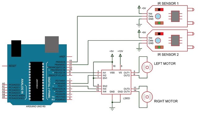
Arduino Line Follower Robot Circuit
Components Required
- Arduino UNO (or Arduino Nano)
- L293D Motor Driver IC
- Geared Motors x 2
- Robot Chassis
- IR Sensor Module x 2
- Black Tape (Electrical Insulation Tape)
- Connecting Wires
- Caster Ball
- Power supply
Note: We have used a pre-built IR Sensor Module that consists of an IR LED and a Photo Diode. If you do not have this, we have explained how to build one yourself.
Block Diagram of the Project
The line follower robot built in this project is divided in to 4 blocks. The following image shows the block diagram for line follower robot.
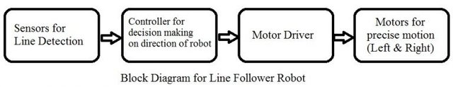
Block Diagram Description
Sensors (IR Sensor): We have used IR Sensor Module as the line detecting sensor for the project. It consists of an IR LED and a Photo diode and some other components like comparator, LED etc.
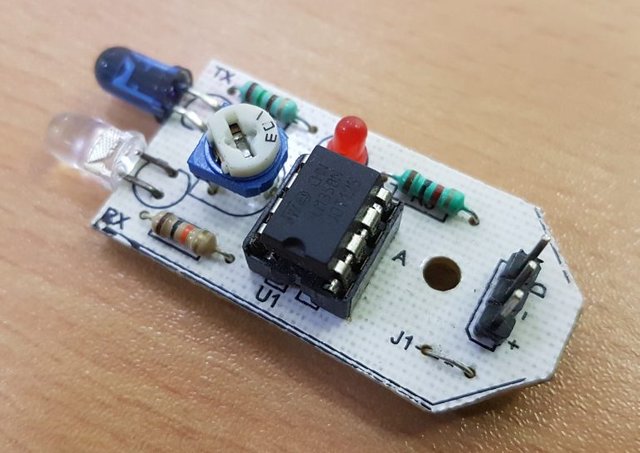
IR Sensor Module
As mentioned earlier, we have used a pre – assembled IR Sensor. In case you do not have one, you can make your own sensor using the following circuit.
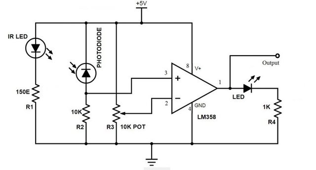
IR Sensor Circuit
The working of the IR Sensor and its scope in this project will be explained in the actual working of the Line Follower Robot.
Controller (Arduino UNO): Arduino UNO is the main controller in the project. The data from the sensors (IR Sensors) will be given to Arduino and it gives corresponding signals to the Motor Driver IC.
Motor Driver (L293D): L293D Motor Driver IC is used in this project to drive the motors of the robot. It receives signals from Arduino based on the information from the IR Sensors.
Note: The power supply to the motors must be given from the motor driver IC. Hence, choose the appropriate power supply which is sufficient for all the components including the motors.
Motors (Geared Motors): We have used two geared motors at the rear of the line follower robot. These motors provide more torque than normal motors and can be used for carrying some load as well.
Working of Arduino Line Follower Robot
In this project, we have designed an Arduino based Line Follower Robot. The working of the project is pretty simple: detect the black line on the surface and move along that line. The detailed working is explained here.
As mentioned in the block diagram, we need sensors to detect the line. For line detection logic, we used two IR Sensors, which consists of IR LED and Photodiode. They are placed in a reflective way i.e. side – by – side so that whenever they come in to proximity of a reflective surface, the light emitted by IR LED will be detected by Photo diode.
The following image shows the working of a typical IR Sensor (IR LED – Photodiode pair) in front of a light coloured surface and a black surface. As the reflectance of the light coloured surface is high, the infrared light emitted by IR LED will be maximum reflected and will be detected by the Photodiode.
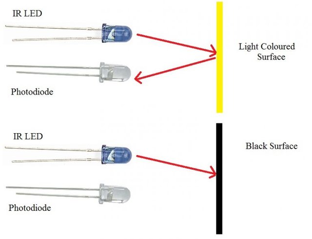
In case of black surface, which has a low reflectance, the light gets completely absorbed by the black surface and doesn’t reach the photodiode.
Using the same principle, we will setup the IR Sensors on the Line Follower Robot such that the two IR Sensors are on the either side of the black line on the floor. The setup is shown below.

When the robot moves forward, both the sensors wait for the line to be detected. For example, if the IR Sensor 1 in the above image detects the black line, it means that there is a right curve (or turn) ahead.
Arduino UNO detects this change and sends signal to motor driver accordingly. In order to turn right, the motor on the right side of the robot is slowed down using PWM, while the motor on the left side is run at normal speed.
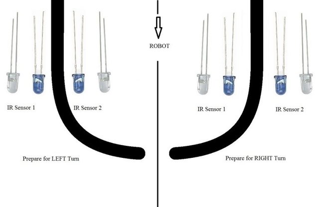
Similarly, when the IR Sensor 2 detects the black line first, it means that there is a left curve ahead and the robot has to turn left. For the robot to turn left, the motor on the left side of the robot is slowed down (or can be stopped completely or can be rotated in opposite direction) and the motor on the right side is run at normal speed.
Arduino UNO continuously monitors the data from both the sensors and turns the robot as per the line detected by them.
CODE
int mot1=9;
int mot2=6;
int mot3=5;
int mot4=3;
int left=13;
int right=12;
int Left=0;
int Right=0;
void LEFT (void);
void RIGHT (void);
void STOP (void);
void setup()
{
pinMode(mot1,OUTPUT);
pinMode(mot2,OUTPUT);
pinMode(mot3,OUTPUT);
pinMode(mot4,OUTPUT);
pinMode(left,INPUT);
pinMode(right,INPUT);
digitalWrite(left,HIGH);
digitalWrite(right,HIGH);
}
void loop()
{
analogWrite(mot1,255);
analogWrite(mot2,0);
analogWrite(mot3,255);
analogWrite(mot4,0);
while(1)
{
Left=digitalRead(left);
Right=digitalRead(right);
if((Left==0 && Right==1)==1)
LEFT();
else if((Right==0 && Left==1)==1)
RIGHT();
}
}
void LEFT (void)
{
analogWrite(mot3,0);
analogWrite(mot4,30);
while(Left==0)
{
Left=digitalRead(left);
Right=digitalRead(right);
if(Right==0)
{
int lprev=Left;
int rprev=Right;
STOP();
while(((lprev==Left)&&(rprev==Right))==1)
{
Left=digitalRead(left);
Right=digitalRead(right);
}
}
analogWrite(mot1,255);
analogWrite(mot2,0);
}
analogWrite(mot3,255);
analogWrite(mot4,0);
}
void RIGHT (void)
{
analogWrite(mot1,0);
analogWrite(mot2,30);
while(Right==0)
{
Left=digitalRead(left);
Right=digitalRead(right);
if(Left==0)
{
int lprev=Left;
int rprev=Right;
STOP();
while(((lprev==Left)&&(rprev==Right))==1)
{
Left=digitalRead(left);
Right=digitalRead(right);
}
}
analogWrite(mot3,255);
analogWrite(mot4,0);
}
analogWrite(mot1,255);
analogWrite(mot2,0);
}
void STOP (void)
{
analogWrite(mot1,0);
analogWrite(mot2,0);
analogWrite(mot3,0);
analogWrite(mot4,0);
}