Advantages of Star Delta 3-phase Motor Automatic starter with Timer
Automatic Star Delta Starter with Timer for 3-Phase Motor
The Star-Delta (Y-Δ) 3-phase Motor Starting Method by Automatic star-delta starter with Timer.
• One line Diagram of Simple Contactor circuit.
• A Simple Circuit Diagram of Contactor with Three Phase Motor.
Abbreviations: ( FOR Star Delta 3-phase Motor Automatic starter with Timer)
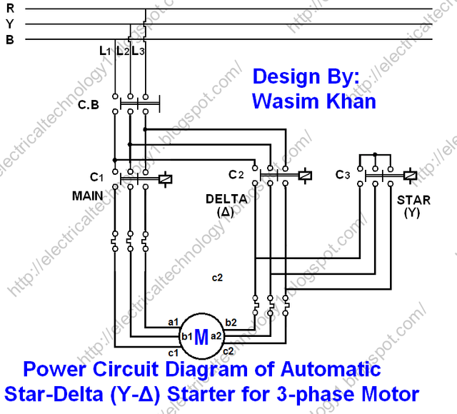
R , Y, B = Red, Yellow, Blue ( 3 Phase Lines)
C.B = General Circuit Breaker
Main = Main Supply
Y = Star
Δ = Delta
1a = Timer
C1, C2, C3 = Contatcors (For Power & Control Diagram)
O/L = Over Load Relay
NO = Normally Open
NC = Normally Closed
K1 = Contactor (Contactor coil)
K1/NO = Contactor Holding Coil (Normally Open)
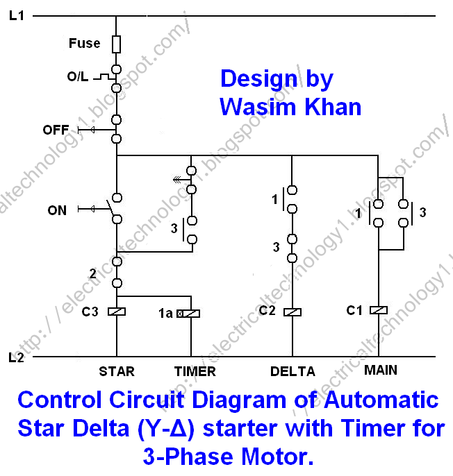
Automatic Star Delta Starter with Timer Wiring & Installation Diagram
 is energized at once and the motor winding then connected in Star. When C3 is energized, its auxiliary open links will be closed and vice versa (i.e. close links would be open). Thus C1 Contactor is also energized and Three Phase Supply will reach to the motor. Since winding is connected in Star, hence each phase will get √3 times less than the line voltage i.e. 230V. Hence Motor starts safely.
- The close contact of C3 in the Delta line opens because of which there would be no chance of activation of contactor 2 (C2) .
- After leaving the push button, Timer coil and coil 3 will receive a supply through Timer contact (Ia) , Holding contact 3 and the close contact 2 of C2.
- When Contactor 1 (C1) is energized, then the two open contact in the line of C1 and C2 will be closed.
- For the specific time (generally 5-10 seconds) in which the motor will be connected in star, after that the Timer contact (Ia) will be open (We may change by rotating the timer knob to adjust the time again) and as a result;
Also read;
(I) Starting & Stopping of 3-Phase Motor from more than One Place Power & Control diagrams
(ii) (ON / OFF Three-Phase Motor Connection Power & Control Schematic and Wiring Diagrams)
• Contactor 3 (C3) will be off, because of which the open link of C3 will be close (which is in the line of C2) thus C2 will also energize. Similarly, When C3 off, then star connection of winding will also open. And C2 will be closed. Therefore, the motor winding will be connected in Delta. In addition, Contact 2 (which is in the line C3) will open, by which, there would not be any chance of activation of coil 3 (C3)
• Since the motor is connected in Delta now, therefore, each phase of the motor will receive full line voltage (400V) and the motor will start to run in full motion.
Also Read; - Main Difference between contactor and Starter.
- A simple circuit diagram for understanding the Working of contactor.
- Why We Need to Install a Starter with a Motor?
Star Delta 3-phase Motor Automatic starter with Timer Power Circuit Diagram:
Click image to
Simple Design and Operation
• Comparatively cheaper than other voltage controlling methods
• Torque and Current performance of the Star delta starter is well.
• It draws two times starting current of the FLA (Full Load Ampere) of the connected motor.
• It reduced the starting current to one-third (approximately) as compared to DOL (Direct ON Line Starter)
Also read: - Three Phase Motor Connection Reverse and Forward Power and Control wiring diagrams
- Two Speeds One Direction Three Phase Motor Connection Power and Control Diagrams
- 2 Speeds, 2 Directions Multispeed 3-phase Motor Power & Control Diagrams
imer-Wiring-Diagram-768x627%20(1)%20-%20Copy.jpg)
hopefully useful for you thank you

