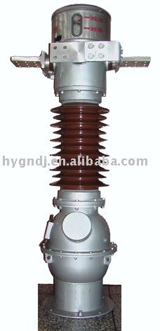
Instrument Transformer and it's application #2
INSTRUMENT TRANSFORMER
In my first post I made known what a power transformer is, it’s uses and external parts. But in this post I will be unveiling Instrument transformer, so please endeavor to read through to grasp the full information in the post.
Due to high voltage and current transmission along the power line, it is therefore very dangerous for engineers working in a power generation ,transmission and distribution to measure directly the voltage and current entering the system,so they make use of instrument transformer to achieve that.Therefore
Instrument transformer is an electric device which is used to transform a very high current or voltage to the level that is user friendly and less dangerous based on the ratio of it’s winding.
Instrument transformer is of two which include the following:
Current Transformer
Voltage Transformer
CURRENT TRANSFORMER
Current transformers typically consist of a silicon steel ring core wound with many turns of copper wire. The conductor carrying the primary current is passed through the ring. The current transformer primary therefore consists of a single turn. The primary winding is usually made the permanent part of the current transformer.It is specified by their current ratio,that is primary to secondary ratio.The primary current may vary depending on it’s source but that of secondary current has a standard output rating which is either 1 or 5 amp.
Current transformer is an electric device which are configured to allow it’s circuit to be connected in series form, with one point been the source of the high current and the other been that of the stepped down current.The ratio for instance can be 100:5amp, it means 100amp enters into the current transformer through the primary terminal and comes out through the secondary terminal stepped down to 5amp.It is used to measure currents of high magnitude. This transformer steps down the current to be measured, so that it can be measured with a normal range ammeter.The primary winding may be just a conductor or a bus bar placed in a hollow core. The secondary winding has large number turns accurately wound for a specific turns ratio.Thus the current transformer steps down voltage and step up current.
They are also used as metering and protection device, in the sense that it is configured to meter out specified amount of current to the system(i.e mostly Relays in the control unit) so when there is fault in the system and the amount of current been metered out goes higher than that already programmed in relay, the relay will immediately respond to this unusual current detected by sending signal to the circuit breaker to open up, there by protecting the whole system from getting damaged by the fault.

VOLTAGE TRANSFORMER
Voltage transformer (VT), also known as potential transformer (PT), are a parallel connected type of instrument transformer. They are designed to step down the high voltage coming from a source to the level which can be measured by a normal range voltmeter without causing damage to the voltmeter and the person measuring it.
The voltage transformer is typically described by its voltage ratio from primary to secondary. A 600:120 PT will provide an output voltage of 120 volts when 600 volts are impressed across its primary winding. Standard secondary voltage ratings are 120 volts and 70 volts, compatible with standard measuring instruments.
It is also used as a metering and a protective device, as that of current transformer, both follows the same mode of operation.

Reference :
wikipedia
quora
electronics hub