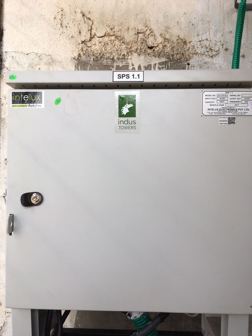
Simple Power Solution
Product Description
.jpeg)
“SPS” is an efficient robust system which has a feature of working and extending power supply on 3/2/1 phase utilization by ensuring load catering on specific phases available without any phase selection. It has provision of working in two ways de-pending upon the settings done as LVD – ENABLE/DIASABLE.
ENABLE Condition:- ( Default Factory Set) - Even if any of the phase is healthy
(> 90V and < 300) , system will allow to utilize the available phases. For this scena-rio ,DG should trigger based on the LB voltage/HRT even if 1phase or 2 phase are healthy. DG should not trigger If all three phases are healthy and LB alarm appears.
DISABLE Condition:- Any phase coming down 90V (Phase Voltage) , all three phases should cutoff, system will sense mains fail followed by “site on battery” and
DG will trigger as per the DG saver logic.
SPS can manage and control the power requirements at the existing unmanned BTS and provide a single point control & monitoring facility for superior, efficient op-erational performance over conventional AMF and Servo Systems. High speed mi-cro controller based controlling & monitoring Interface.
SPS also controls & monitors the generator performance. With the input mains supply failure; the unit automatically switches ON the diesel generator unit and transfers the load to it. SPS is built with operational logic, where user can set gene-rator ON / OFF time (maximum) based on 48V/24V DC Power Plant Battery voltage status and Shelter Temperature status.
Along with the power management function, SPS also monitors the auxiliary function like fire/smoke. It also extends the DG and mains status alarms to Base
Transmission System (BTS) with potential free contacts.
SPS is having the following units to perform the operation.
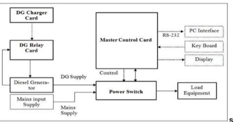
Master Control Card (MCC) - Monitor and control the complete operation of SPS.
Power Switching Unit (PSU) – Provides interface to Input mains supply and generator supply and load distribution
Master Control Card:
“Master Control Card” (MCC) primarily function is to monitor, display and control the SPS op-eration. MCC is interfaced with Power Switching Unit (PSU) to monitor mains input supply, DG supply and also control load connection with mains and DG.
As long as the mains supply voltage is within the pre-defined voltage range, the mains supply is given to load at the output. When mains supply voltage is off or out of the pre-defined voltage range then, MCC will switch on the DG, if 48V/24V DC Battery Bank low or Temp high condition occurs. DG control unit will switch ‘ON’ the DG and report thesame to MCC. Now, MCC will switch the load to DG output.
Keypad, LCD display, interfaces are provided to the Master control unit so that the user can view the display data like Voltage, Currents, Battery Voltage, temperature interactively.
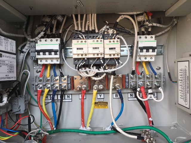
Power Switching Unit
“Power Switching Unit” PSU is equipped with distribution panel (MCB’s), contactors. MCC control PSU through interface connection with contactors. Input mains supply, DG supply and load (Equipment and A/C) are terminated on MCB’s provisioned in PSU.
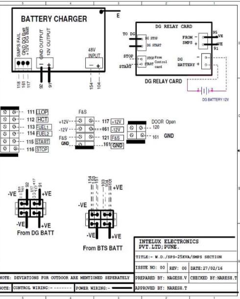
DG Battery Charger:
Battery Charger is one of the device it converts 48 V DC to 13.5 V DC to charge the battery present in diesel generator.diesel generator need excitation to run and that excitation by DC Source called Battery.
1.DG Battery Charger is powered up through BTS Battery Termination.
2.Automatic DG battery charger with constant current charging facility. Charger is suitable for charging the SMF/Conventional battery up to 150AH.
3.Generator controller with start, stop relays of 40 Amp rating & push button to start/stop the DG in manual mode
4.Remote Auto / Manual mode selection for DG start/Stop is provisioned in Panel
.jpeg)
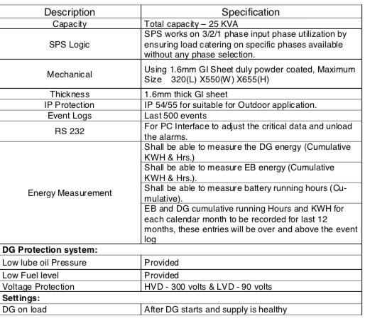
Technical Specifications of Simple Power Solution
.jpeg)
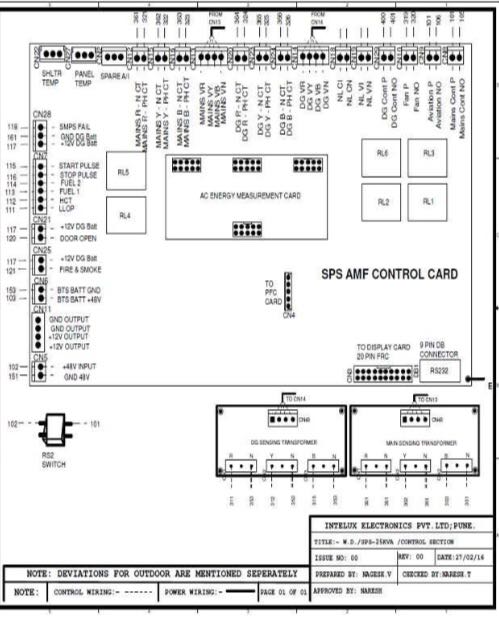
Circuit Diagram of SPS
Power Flow Diagrams
.jpeg)
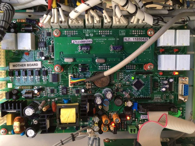
Mother Board
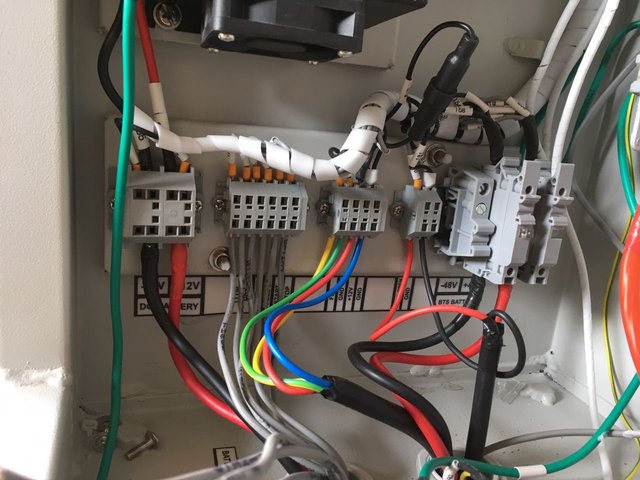
Other Wiring needed to Automation and Fire and smoke connections
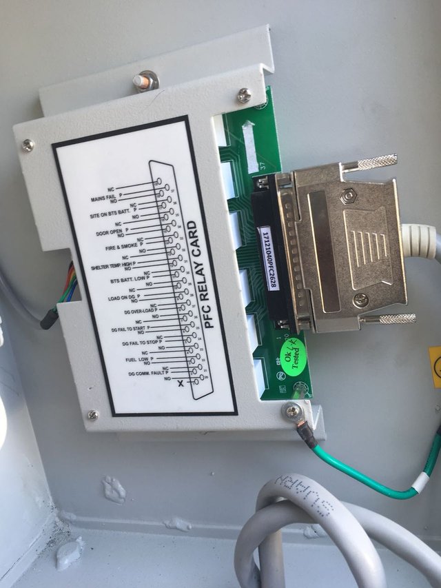
PFC Card:-
PFC Mean Potential Free Contacts, this card does not have any potentiality. It means the two contacts are connected any direction .jpeg)
Basic Information:
No material should be left inside the panel.
Tools to be used must be insulated covering or to be insulated with insulating tape.
Always provide a free airflow in front of and above the cabinets / individual units.
Equipment with unprotected, live parts must not be left unattended.
Take off Metal bracelets; rings etc. That can cause short circuits in equipment.
High Voltage:
Voltage up to 300V AC is used in the SPS. General carelessness, misuse or negligence of safety rules may lead to death.
Panel shall be switched off before any maintenance activity starts.
Connecting Cable:
Input and output connecting Cables should be marked both the ends.
Electrostatic Discharge (ESD):
Integrated Circuit can be damaged by Electro Static discharge. Always use an
ESD wrist strap connected to chassis or the earth while working with printed circuit board assemblies and components.
Authorization:
For recommended authorization, Keep the equipment locked and keep Key with the responsible person.
Training:
User/Operator, who has got training about the equipment, is only authorized to operate the equipment.
After finishing maintenance Work Disconnect any connected equipment. Re-store the equipment to its original state. Make sur that all the outgoing alarms are connected as per the drawing and all the measures taken are noted in the logbook
Installation:
Check the physical condition of the panel.
Place the SPS properly at site place and fix the mounting holes with grouting bolts.
Check the loose connections and tight all connections. Mount the DG relay card properly at the DG.
Remove the sleeve of the cables (Mains, DG) from Mains box & DG alternator. Separate DC & AC cables at SPS.
Place the relay card properly at DG.
Remove the sleeve of cables (Mains input, DG input) up to bottom of SPS.
Verify the connection at alternator of DG.
Give the ground connections of main ground at SPS body.(Don't mix with DC ground)
Give the connections of Battery +VE, Battery -VE, start &stop from DG panel to relay card.
Give the connections Battery +VE, Battery -VE, start &stop from relay card to the connector provisioned at the termination box, side of panel.
Give the connections LLOP, HCT, Fuel 1, Fuel 2, and GND from DG panel to the connector provisioned at termination box, side of panel.
Give the connection of -48V from rectifier to SPS (-48V, GND).
Check the load distribution at output.
Give the connections to Fire &smoke detector. Give the connection from DOOR open sensor.
Give alarm connections from PFC card to Alarm box.
How to overcome SPS Tampering?
Please reply ASAP