Week Two of How to Build Electronics: Components and Practical Application Pt 1
Components and Their Practical Application
Hey there Steemians. As promised, I am posting part two of my Build Electronics Series. Today we are going to talk about electronic components. What are some common electronic components? How can they be used?
Lets begin with the most basic electronic component of all, the power source.

An adjustable voltage power supply
Power sources. Power sources are what is used to power your circuit. Now this doesn't just have to be a AA battery or a cord plugged into the wall. There are a variety of different power sources available. Solar power (using solar energy and a special phenomenon called the Photovoltaic effect), hydro power, thermal energy, and even magnets can be used to generate power for your circuit. The important thing is that however you choose to power it, you dont overpower or underpower your circuit. If you provide too little power, your circuit probably wont even turn on, or it will operate very slowly (For example, one time I built a robot and only supplied it with 5v of power. It moved at a snail's pace until I upped it to 10v! I kept wondering if I had soldered something wrong, or written bad code - but really my robot didnt have enough power to execute the code as quickly as I was asking it too. If you ever encounter this problem, double check that your giving your circuit enough power.) If your provide too much power to your circuit, your parts will burn up or blow up. Trust me! Ive burned out enough LEDs to know. You’ll start to smell a foul scent, and you’ll know you’ve overdone it.
A solution to this problem is to supply less power. Check the data sheets for each piece of your circuit to make sure it can handle the current and voltage your giving it. If it cant, you can compensate with resistors.

An assortment of resistors
Resistor. Speaking of resistors, lets go into a little detail about them. Resistors are generally used to reduce current. Say I have a 9v battery, and a motor that can only handle 5v. Instead of blowing out my motor, I can use resistors to reduce current flow to a level the motor can take. Resistors are commonly used in this fashion with other current sensitive components.
Resistors in series vs in parallel. If you guys remember when I talked last week about series vs parallel circuits. In a series circuit, the current runs straight through the components in one path, but in parallel the current has more than one path in which to travel. Remember this rule when trying to calculate resistance in your circuit. In series, resistance = the sum of all the resistors. In parallel, it really depends how many resistors you have. You have to remember each one is drawing a current. This picture explained it well:

Potentiometer. Think of these as adjustable resistors. By turning the knob, you can adjust the resistance. These are commonly used in audio control devices.

A Potentiometer. Some guys I know call them "pots", so if you hear them referred to by this name keep in mind this is the component they are talking about.
How to wire:

The analog wire would feed into a micro controller in this diagram. The micro controller could then read the potentiometer's analog value, on a scale of 0 to 1023. Depending on how you program the micro controller, different values would result in different actions being taken.
Capacitor. The capacitor is a key component in almost every circuit. You will find them in so many things, from TVs to radios to cars, to the computer your staring at right now. What capacitors do is they store a potential charge. Capacitors are rated in farads, named after genius electrical pioneer Michael Faraday, an extremely small unit. Capacitors can store energy even when disconnected to a circuit, acting almost like a temporary battery. They can also be used for super cool science projects, like super awesome lasers. Because capacitors can store energy, discharging them all at once can produce a huge burst of energy, enough to power a laser blast.
There are many uses for capacitors, and its important that you learn to use them in a circuit.
Here’s a sample circuit you can build on a breadboard at home to charge a capacitor.
Parts needed: +SPDT switch
+Matching resistor
+Capacitor
+Breadboard jumpers
+Green LED
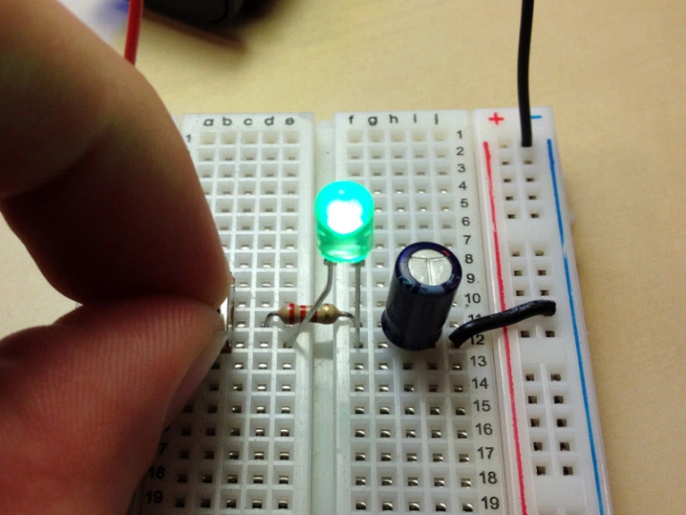
Wire as shown here(Credit to modolect blog for idea and images)
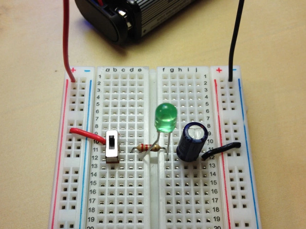
Now flip the switch. When the LED turns green your capacitor will be charged!
Transistor. The amplifiers. Transistors are designed so that small changes in voltage coming into the base of the transistor result in large changes in voltage coming out of its emitter. Transistors can also be used as switches. Transistors are commonly applied in many circuits, and are a key component in almost every electronic device around.

A transistor
Switch. This is pretty self explanatory. Switch ON(closed), electricity flows. Switch OFF(open), electricity doesn’t flow.
How to wire a switch. This is the trickier part. What your going to want to do is wire a hot(positive) wire to the switch, and a hot(positive wire) coming out of the switch. Turning the switch on will close your circuit and make the electricity flow. Turning it off will break the circuit and prevent electricity from flowing.

various switches
Voltage regulators. You can use these to stabilize voltage current. If your power source varies alot in voltage output, say your powering your circuit through thermal energy or chemical reactions or something not as stable as you need it to be. You can use these to stabilize the current. Keep in mind these need a DC current to work, so you may have to use capacitors to filter out any residual AC current (if any exists).

A voltage regulator
Diodes. There are many different types of diodes, many beyond the scope of this work, but basically a diode has two terminals and tries to conduct current in one direction by having one path have really high resistance and the other really low. Electrons will naturally gravitate to the path of lowest resistance giving you a nice flow in one direction.
They can be used in logic gates, ionizing radiation detectors, and even temperature measurements. How exactly this is done is again beyond the scope of this article, as this is intended to introduce beginners to the world of electronics.

Two diodes
LEDs. Your probably familiar with these, but in case your not LED stands for light emitting diode. This is an LED -
The current runs through the anode and out the cathode. When supplied with the proper voltage, the LED will glow! But dont overdo it, as Ive burned out quite a few of these from adding to much power, which overheated the internal components of the LED and burned it out.

An image of the internal workings of an LED

A colorful LED display
Integrated Circuits. Imagine if you could downsize your circuit and put it inside a tiny chip. That is basically what an integrated circuit does. Each one can perform a different function depending on what is inside it. The 555 Timer for example, a very popular chip, can provide time delays in your circuit.

A handful of integrated circuits
Steemit wont let me post anymore images here - so I am going to write a part 2 article explaining LCD Displays, Micro Controllers, Transmitters, and Receivers.
As always, if you dont understand something dont hesitate to ask!