3D modeling the F-14D Tomcat [#2] - A How-To guide based on 3000hrs project time
Burn Steemians, Burn! In this second part of my 'little' project I'll go a bit more into detail on the modeling process, handling Blender and progress in the first couple of months.

This is the default screen as shown last time. Nowadays it looks like this:

If you had told me back then that eventually I'll get to this point I wouldn't have believed you for a second :).
Anyway the way to start is very simply get some blueprints. Now with this aircraft that's easier said than done, the design dates back to the late 60s and no matter which one you chose they all have their flaws. I eventually purchased some from a company that had scanned the original Grumman blueprints for 'Project 303' which was the internal code of what would become the F-14 Tomcat.

These prints all needed a lot of work in Photoshop to get them usable and in the end it will always be a combination of sources that get you where you wanna be.
Default setup is front, rear, top, bottom, left or right and a 3D viewport (as can be seen in the lower right). Blender lets you customize this beautifully and each window can be multiplied, expanded or collapsed at will. You can also create a view which I recommend which is a 3D full view but with the main menu on the right still showing. Like so:

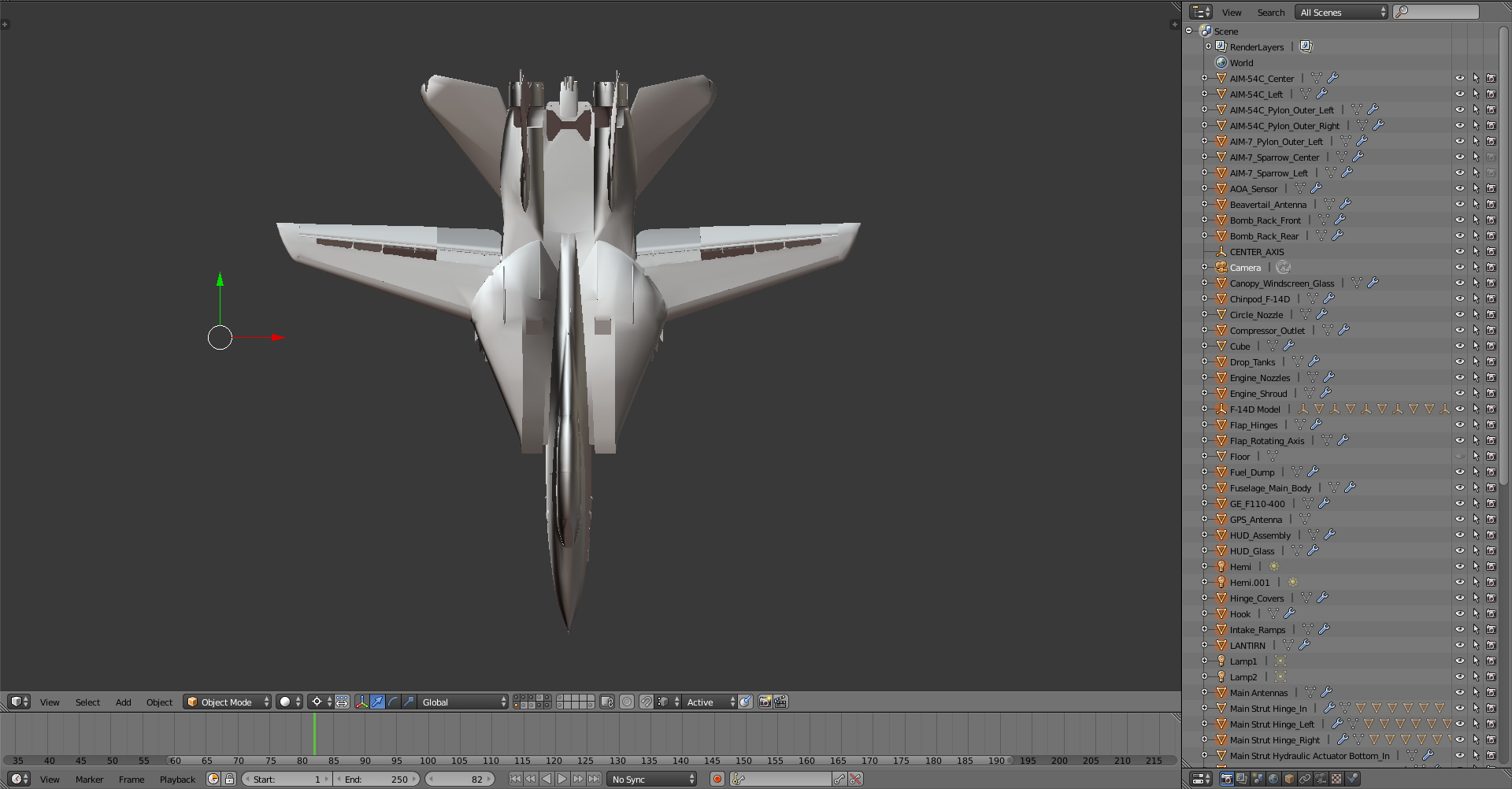
What you see there on the right is the object list for the entire model. I only got around to sorting, naming and arranging these last week. This is something I'd recommend to do right from the beginning. It saves you a ton of time later on if you think about what objects you'll need, what groups they'll be in and what to call them at the start. Even if you miss some, it will help you stay organized and not get lost in the details (which happened to me uhh...around a 200 times).
So let's get into it! Part 1 left off with this super basic piece of the airplane:

It's always a good idea to just start with a certain piece of whatever your modeling. In this case every part is complex and most of them move and have cables, actuators and other stuff connected to them so in order to not go completely crazy just start on one piece.
Modeling Philosophy
At this point I have to mention that today I know there's two approaches to modeling so called 'box-modeling' where you extract and shape everything out of one initial primitive (usually a box) or 'point-by-point' modeling where you literally go from vertice to vertice and shape the body that way. I can't tell you which way is the right one. I ended up combining point by point modeling with a bit of extrusion and automated manipulation (will explain these later) in order to get the right shape.
One thing to remember in modeling is that there is no perfection. It just never ends. So remember: When it looks right, it is right.

Ask any Tomcat pilot or mechanic and they will tell you this nose looks right. You won't find another model on the net (except for one which I know of that has 1 million+ polys) that gets this right. Is that down to my master modeling skills? No. Unique sources? No. I just did tons of trial and error and perspective matching with 1000s of pictures until I got it to look right. Mind you it isn't perfect.
Point by Point

So you just put a point somewhere and start extruding another one out of it and so on, alternatively do that with a plane or even a cylinder. Follow along your print and watch for matching overall shape and proportion. Details can always be amended later.

Check your perspective and correct for the different points of view. You can also use photos but I recommend a combination of both. In this case I ended up completely reworking the whole model so I basically built it twice. Due to faulty blueprints a lot of details were off BUT from the beginning I always took a look at each component and checked it against reference material. Again, if it looks right it is right.


Slowly crunching through the form, engine intakes, engine pods (basically the casing of the engines and intake), topside of the airplane and the glove. The 'glove' is literally the centerpiece of the F-14. It is made mostly out of titanium and structurally the most rigid component of the whole thing. It holds (like a glove) the swing wing assembly - the characteristic design feature of the Tomcat. For comic relief here is an old Grumman ad explaining it:
I actually couldn't find it just now so here some motivation to read on:
With that out of the way at some point you'll have your shape far enough that you can continue to add other parts such as the nose:


All a bunch of quads as you can see. Back then I literally just extruded and built the model like that - not very sophisticated but it did the job. The problem this leads to is a non-smooth surface which will show up later on especially when rendered. The way you avoid that is to model a super basic shape and then using the subdivision function add in additional geometry to smooth out the shape. I only later realized the powerful nature of this approach.


In any case eventually I got to something like this:

If you then smooth out the faces it begins to look representable:

Adding some simple vertical stabilizers it begins to look like an airplane:

Blender Commands, Shortcuts, Functions
Before moving on a word on how to actually operate the program and customize the display.
In Blender you operate the program primarily with the mouse. The right (RIGHT) button selects, the left confirms, the centerwheel is used to rotate the view/camera.
**There are only a few really important keys namely:
'tab' switches between edit mode and object mode, in edit mode you edit your geometry, in object mode you select objects, join them or seperate them etc.
'ctrl'+'e' bring sup the edge manipulation window
'ctrl'+'f' brings up the face manipulation window
'shft'+'a' brings up the add geometry window
'e' is the extrusion command, selecting a vertice, edge or face and pressing 'e' extrudes the shape and you can move the mouse in the desired direction
'x', 'y' and 'z' are your spatial direction commands meaning selection an edge and pressing 'e' followed by 'x' will move the edge along the x-axis, 'y' along the y-axis and so on
's' scale an object in any given direction (xyz)
'shft'+'s' brings up the cursor manipulation menu
'r' rotates a selection in any given direction (xyz)
'z' toggles wireframe view, especially for selections very important**
'h' hide selection
'shft'+'h' unhide selection
'alt'+'h' hide unselected
'ctrl'+'i' invert selection
'p' separates a selection meaning whatever geometry is selected when pressing 'p' it will become its own object
'ctrl'+'j' will join objects meaning whatever object is selected will be joined together and when you press 'tab' now it will all be editable as one object
'l' selects a separate part within one object, say you have two boxes in one object, hovering the cursor above one and pressing 'l' selects that one box
'b' box selector once you press it you can draw out a box with the mouse and anything within it will be selected
'c' is a super useful selector tool which is basically a small circle, by turning the mouse wheel you can increase and decrease its size, left click selects, right click deselects.
'a' selects all, press it again and everything is deselected
With these few commands you'll be able to go very far in Blender!
Lessons Learned and the Bottom Menu
There are some important lessons learned I'll gladly share with you. On the bottom of the menu you see a bunch of icons:
From the left:
'object mode' that tab shows which mode you're in, you can also change the mode by clicking and selecting
'the white ball' indicates the view mode, this one is solid meaning the shapes are filled and displayed, click on it and you can go through wireframe, etc. modes
'the cross' indicates your mode of manipulation, basically the standard means you move/manipulate ONLY what you have selected, the next mode 'proportional editing' means moving one edge will affect other edges in the vinicity depending on your preference, 'individual origins' means you can manipulate geometry dependent only on the individual geometry
'the three blue dots' this is often a problem as sometimes you'll find yourself unable to edit something no matter what you do, select your object and press this and you'll be able to edit it's direction
'the blue arrow' indicates that you're in 3D cursor mode meaning whenever you click a point or edge or face this cursor comes up and you can right click on any of its axis and the geometry will move according to your input
'global' this is the program setting for direction, global means direction from the center point and is often useful, if on the other hand you have a plane and it's tiled 45 degrees around x and you'd like to extrude up and away based on the 45 degree plane you can click this and change it to local and the directions will now be based on the local object specific center point
'the magnet' sometimes useful when combining stuff, when this is activated it automatically joins together points based on a certain proximity they have to eachother
'the grey dots' these are your different layers in the scene, up to 20 you can move objects to and from one or the other
'`' selects all layers, press it again and you're back to your initial selection
Whenever you add a mesh and find yourself unable to see it or it's not aligned to your view (say front view) press 't' and look at the bottom left of the menu, now click the radio button next to 'align to view' and the mesh will be aligned to your current view.
In editing mode you get some additional buttons mainly a 'point box', an 'edge box' and a 'face box' these buttons determine the editing mode you're in, in point mode you select points, in edge mode edges and in face mode.........faces.
One additional button is the 'limit selection to visible' button next to those. If engaged you select all geometry visible from your view ALSO the stuff that is on the other side of your model. If you don't want this disengage this mode.
Menus

When you begin to play around with Blender there are two important menus one to the left and one to the right of the viewport activated by 't' and 'n'.
Above you see the left one activated by pressing 't'. This menu is super useful when in editing or object mode and you should play around with it a lot. Will get into the details in the next part.
The Nose
Even this early in the project I felt dissatisfied with the way the nose looked and the whole front fuselage for that matter. As I said a part that not many people get right and I absolutely understand why. What I did was I separated the geometry and then looked at it from the rear, overlayed my Grumman 1960s blueprint and like the scale modelers went through it in circular fashion.

I outlined one section and then hid it, then went on to the next.

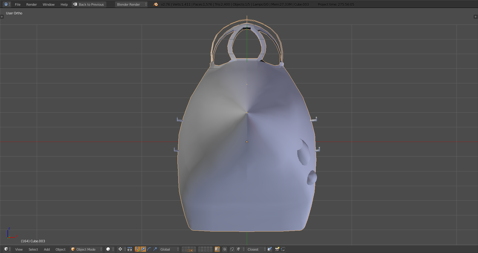

The gunport you see on the bottom was created by adding a cylinder ('shft'-'a' > mesh > cylinder), go into edit mode by pressing 'tab', select all by pressing 'a', move the cursor to the selection by pressing 'shft'+'a' > move to selection.
Now you can press 's' and any of the axis keys and by moving the mouse you'll see how the shape transforms either longer or shorter, narrower or wider, etc. by playing around with that I was able to create a banana type shape. I then rotated it along x by pressing 'r' and 'x' and moving the mouse until I had the right angle. More next time.
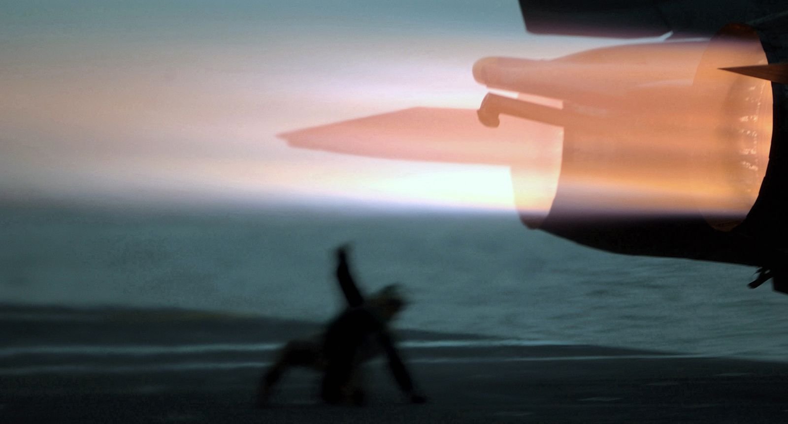
Motivational Impressions:


Yes we will get to that eventually :).
Steem on!!!
holy beejezzzzuss. have you ever watched the show battlestar galactica? They built a fighter by tearing down an existing fighter. They must of done something very similar to this! 3000 hours is a shit ton of time man! The only real way to see if the nose works, is to build one and throw that sucker in a wind tunnel! Good job!
I've worked on models that were thrown in a CFD simulation - THAT is something else. That said the simulation this is for does take into account drag and so on so the model has to be accurate on major surfaces but nothing close to CFD or wind tunnel of course. Also with that kind of stuff you need one solid body which is a whole different animal.
It is a lot of time but I've basically learned blender and 3D modeling alongside so it might be a bit misleading.
The Battlestar Galactica thing you're describing does sound a lot like what I'm doing yes. That's the fate of all military AC builders through cuz we never get the full insight into the actual RL design due to 'classified'. In this case it's even worse because the F-14D data will remain classified for a looong time even though all US NAVY airframes have been almost completely destroyed meaning shredded.
what is your background in? work wise?
I'm a freelancer in head hunting/recruiting for global engineering and logistics/warehousing projects.