How To Make A Timer Circuit Using 555IC

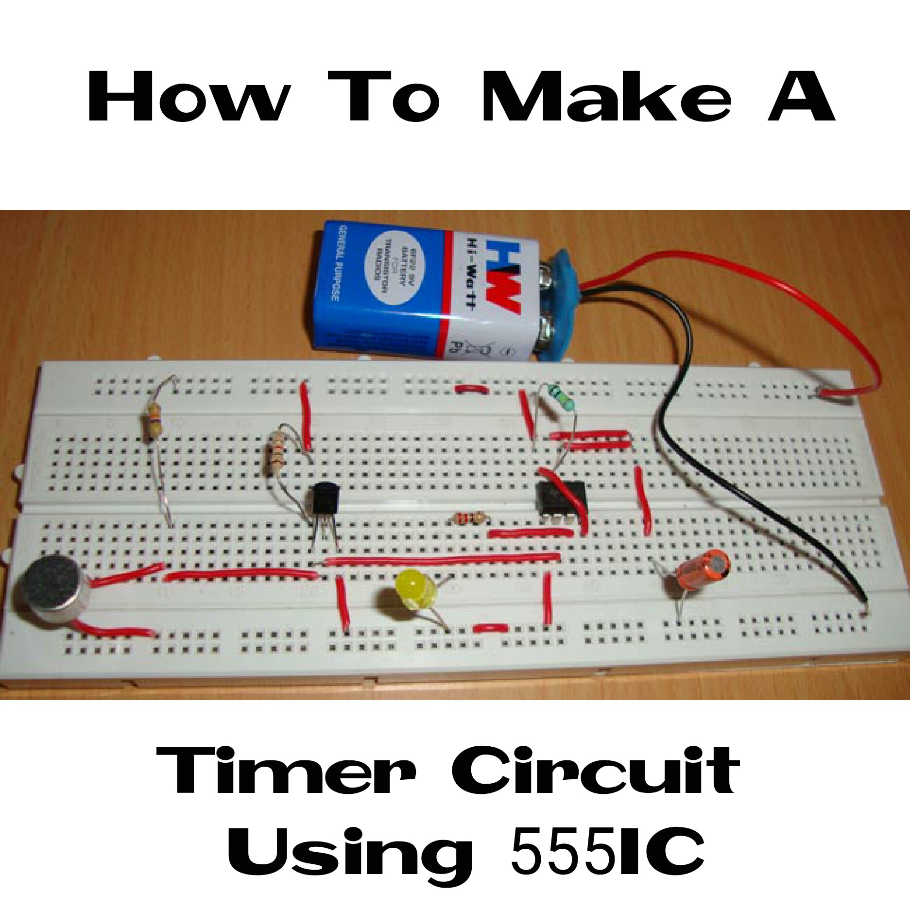
This timer circuit using 555IC can be used as an alarm after certain time. In daily life there is many timer circuits we may use but how about designing and implementing your own timer circuit in your home.
This circuit is very simple to understand and also to implement. Lets see how it works.
WORKING OF TIMER CIRCUIT USING 555IC
The 555IC works with an speaker which serves as an indicator apart from the LED.
It is a pulse generating circuit in which the duration is determined by RC network connected external to it. Here a switch S1 is given as reset push button and when the switch was pressed the timer starts and green LED D1 glows after the end of timer(pulse generated).
Here the capacitor C1 and C2 discharges the voltage stored in it and it decides the timing of this circuit.
When the trigger pulse is applied output is forced to high and it remains high until capacitor is completely discharges if you need more time you can connect high values of capacitor and resistor to it.
The pot R4 can also be used to vary the time duration of your timer circuit. Instead of LED you can also use Relay or any other component based on your need.


I am now following you! Be blessed and patient with your steem life adventure! Seriously, best wishes!
Thanks!
Resteemed your article. This article was resteemed because you are part of the New Steemians project. You can learn more about it here: https://steemit.com/introduceyourself/@gaman/new-steemians-project-launch