Lenovo W530 2019 | Do-It-Yourself: Replacing CPU/GPU Thermal Paste & Heatsink Assembly /// Pt. 3
Welcome back to my W530 restoration, upgrade and preventative maintenance journey. This notebook is a workstation model built in 2012 as a 2013 model with a pretty highend CPU even by today's standards - the i7 3840QM. It is a quad core chip with 8MB L3 cache and a maximum clockrate of around 3.8GHZ. I bought it refurbished from a Thinkpad specialist in Germany so I knew it had been disassembled and cleaned before.
Unfortunately the CPU reached temperatures of 100C+ degrees under load and while these 'pre-low-voltage' Intel CPUs (drawing 45W max) are capable of running well into the 90s and 100s while still maintaining high clock rates without taking any damage it is always a good thing to keep things as cool as possible.
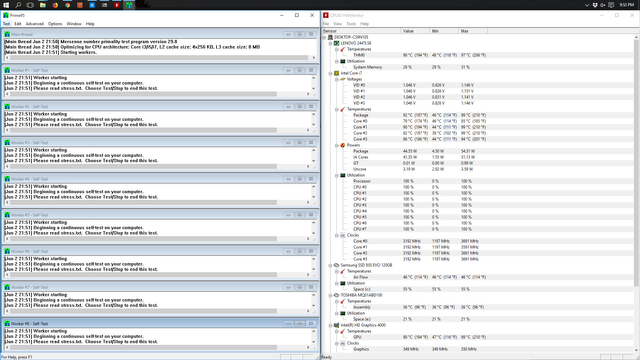
As you can see above while running the P95 torture test the CPU reached a max of 99C degrees when I took this screenshot and would later peak out at 102C degrees with the fan running on max at around 4.400rpm to keep things well...at around 100 degrees - much too hot for my liking. Aside from reducing the life expectancy of all kinds of components especially the CPU this kind of temperature also lowers the maximum achievable sustained clockrate. As you can see the clockrate at 100C degrees averages out at around 3192MHZ which is well below the max of 3791MHZ or 3.8GHZ.
What happens here is the CPU increases its clockrate depending on required computation and with the increase in temperature that goes along with that the fan picks up speed to reduce heat production. At some point under sustained load the CPU reaches its maximum clockrate but the fan can no longer adequately channel the heat away from the chip through the heatsink so the CPU reduces its clockrate to the point where it can hold temperature at max fan speed.
The best thing to permanently lower temps is to clean the fan in the heatsink assembly, clean the copper plates that sit on top of the chips and replace the thermal paste - preferably with a high quality, high performance compound.
To achieve this the heatsink assembly has to be removed completely which we'll do today!
Removing the Heatsink - Preparation
Before starting any work on any Thinkpad product you're well advised to download the Lenovo hardware maintenance manual for your specific machine. They're freely available on Lenovo's website and for the W530 you can find it here:
https://thinkpads.com/support/hmm/hmm_pdf/t530_t530i_w530_hmm_en_0b48474_02.pdf
It details step by step virtually the entire disassembly process down to the raw chassis - very useful even if you do know your way around Thinkpads.
Next get your tools, wipes and cleaning products ready:
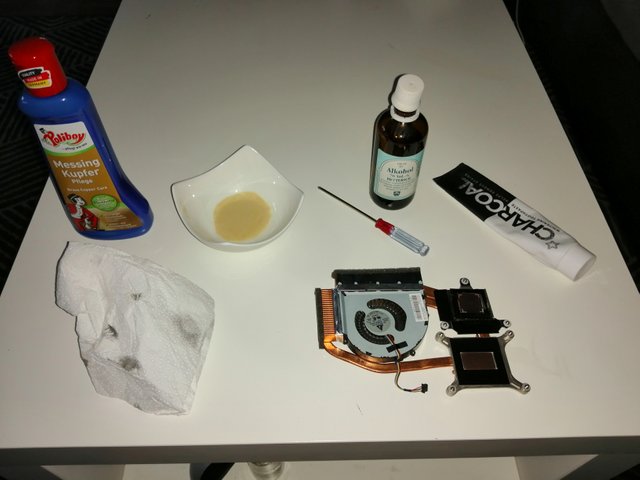
That is pretty much all you need for this operation:
- Paper towels
- Mini Philips head screw driver
- Copper polish (any other metal polish will also do)
- Some alcohol to disinfect and also remove any access residue
- a small dish/container for the alcohol/polish mixture we'll be using
- toothpaste for the final grit removal process
- thermal paste (in my case using Arctic Cooling MX4)
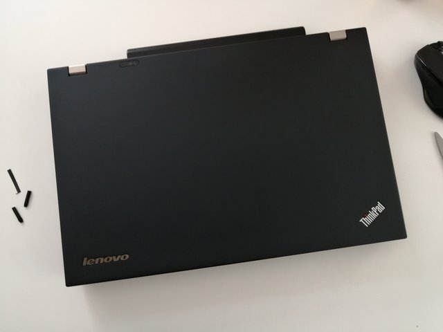
Removing the Heatsink on a W530
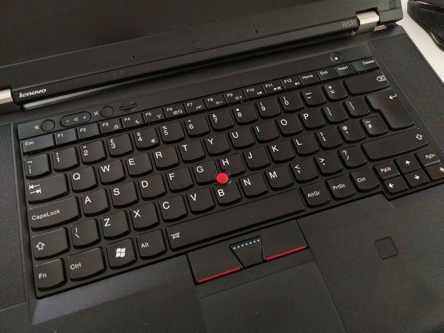
First step as before is to remove the keyboard:
Only this time we'll also be removing the palmrest so we'll take out all relevant screws on the bottom side:
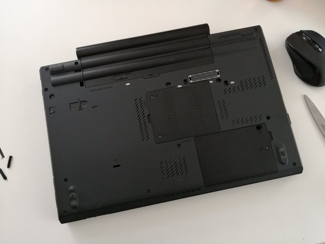
The following components will have to be removed before turning the machine around again:
- any SD card in the SD slot
- any Smartcard in the slot
- Ultrabay cartridge
- maintenance door
- harddrive door and drive
We then unscrew the two keyboard screws:
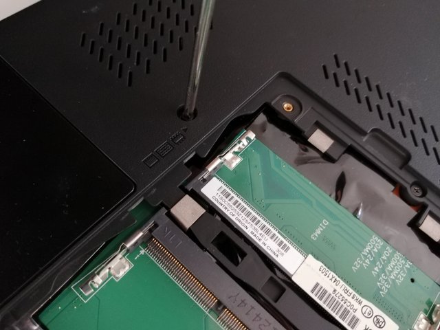
Following this we'll remove all screws on the bottom side except the two screws right below the screen hinges - do not remove these!.
The machine can now be turned around and screen can be opened - beware of the now reduced weight of the bottom side so do not open the screen more than 90 degrees otherwise the machine will tip over!
Remove the keyboard by gently sliding it back until the front pops out and remove the cable connector:
Upon removal we can now take the palmrest out. Before doing that disconnect the device interface cable by lifting up the dark grey arrestor and pulling the cable out vertically:
To better reach it I actually pulled the white connector as well:
Pulling the palmrest
\

This is a simple process but it needs to be done right to avoid breaking any of the plastic pins. Make sure all relevant screws are pulled before you begin to lift the palmrest!
Step 1 Have your screen open straigth at 90 degrees and begin by lifting the front left corner upwards away from the chassis bottom. Move slowly but keep pulling until you hear the first click.
Step 2 Continue to the right along the front edge and pull the palmrest you will hear one click after another. Once you get to the front right corner you need to carefully hold the internal magnesium frame down while continuing to pull the palmrest up (this is why we had to remove the SD card and smartcard). The critical spot is around the headphone jack. Make sure you pull the palmrest only and not the frame.
Step 3 You can now light the sides along the speaker covers until you get to the back where the screen hinges sit. Lift up the palmrest until it is angled sufficiently so it can pop out of the rear arrestor hooks. You might need to close the screen slightly so you can pull it up and out.
I just described a process that is one tiny picture with two arrows in the maintenance manual. Work slowly and carefully and you'll be able to remove it without any damage.
And so we go from here:
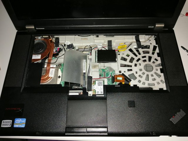
To there:

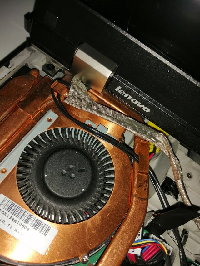
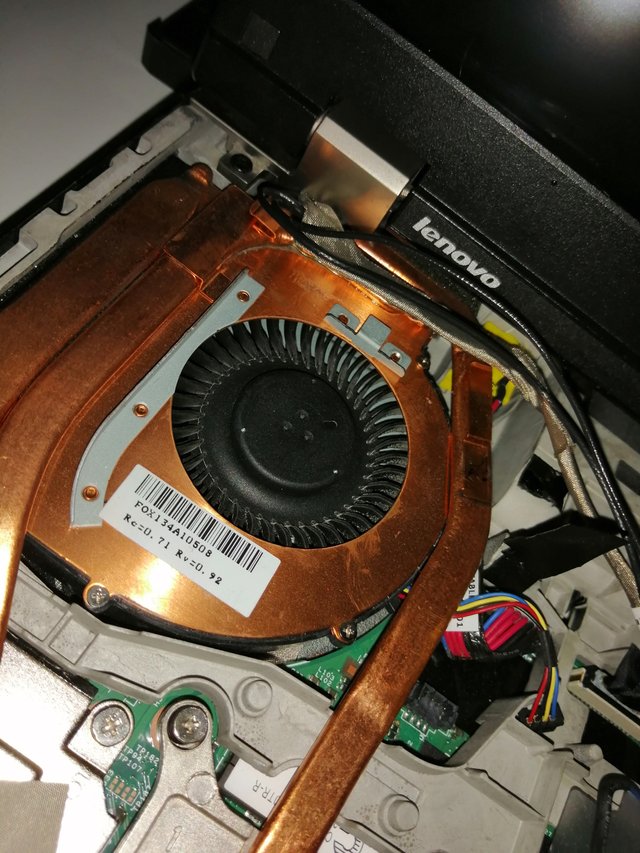
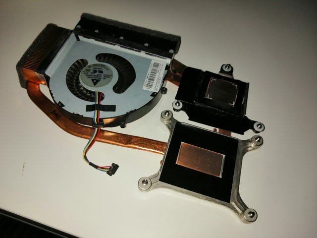
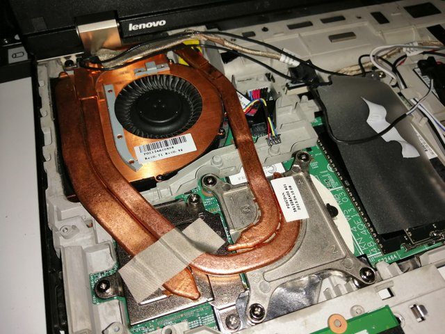
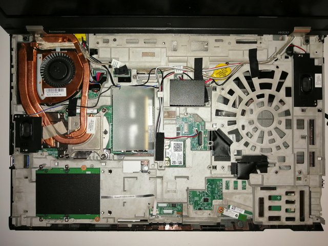
And here is the centerpiece of today's operation:

Pulling the heatsink
First thing is the removal of the left speaker as that sits on top of the assembly. Remove the two screws and carefully pull the cable from the heatsink. It is fine to simply rest it on the right side of the chassis.
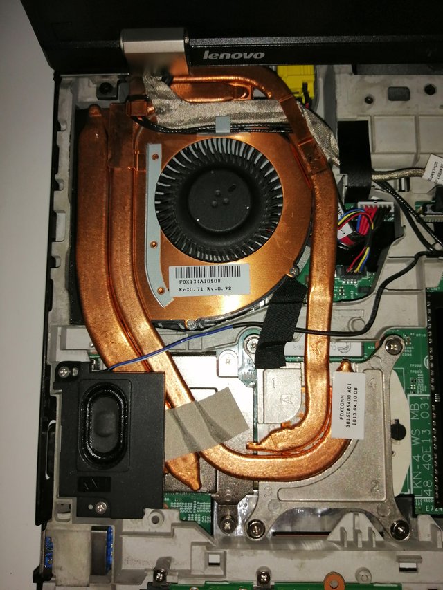
Now start to unscrew but not remove the 7 screws that keep the heatsink in place over the CPU and GPU. All W530s have dedicated graphics chips so it will always look like this. However, on some T530 models there might only be the CPU so in that case you would have less screws but the process is still the same.
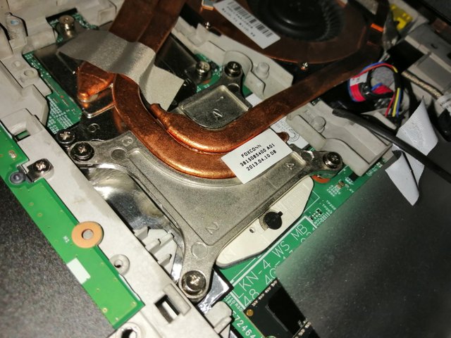
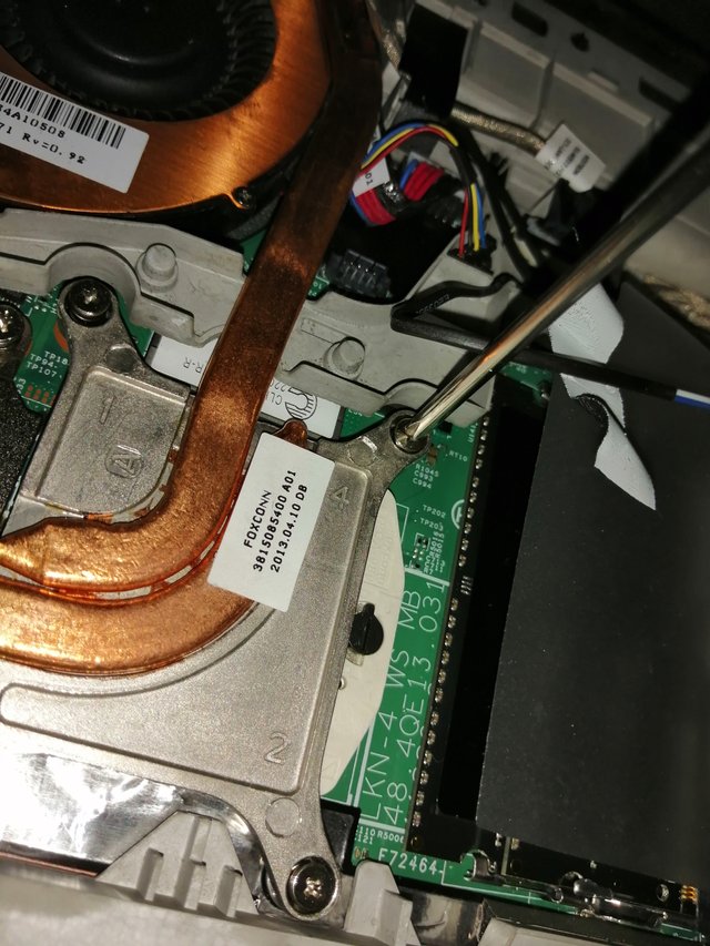
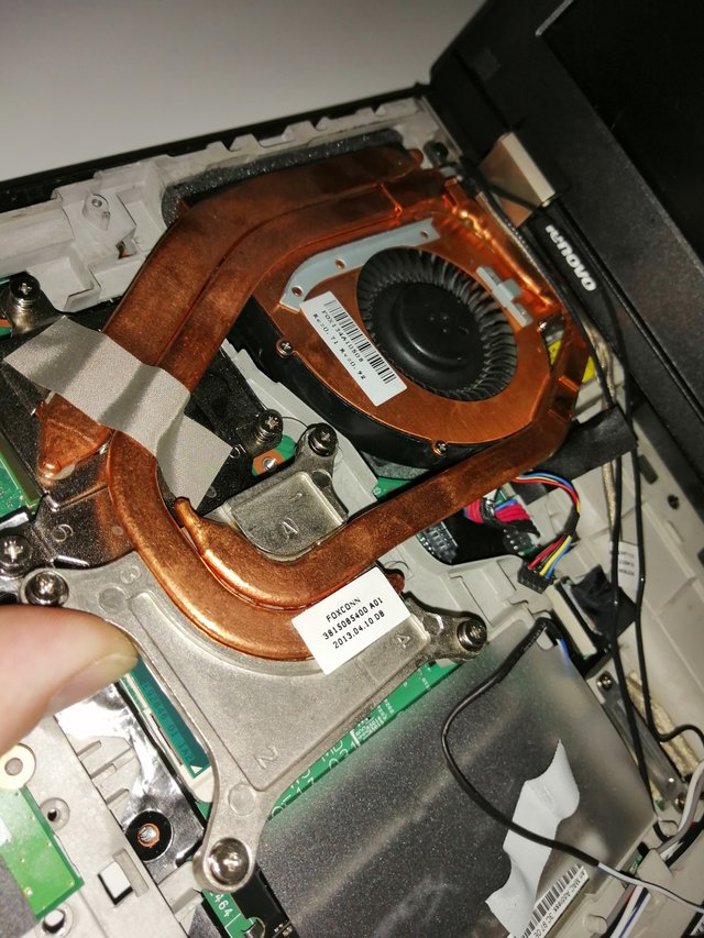
It is recommended to loosen the screws in an opposing order so start with top right, then lower left, then top left and finish with lower right. The three screws on top of the GPU can be losened in random order.

Now before starting the removal make sure all cables are detached from the heatsink, there are three hooks on top for screen and antenna cables so slide those out and leave them.

Start at the front right corner and see if the heatsink can be lifted from the board, it won't go up far this is just to check that all 7 screws are actually detached from the board.

And here we get a first glimpse of our old thermal paste (way too much applied):
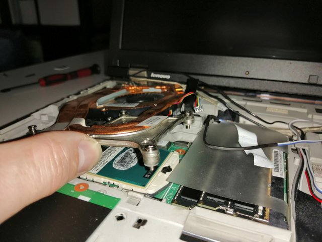
What follows now is a lengthy, painful and quite delicate process of pulling the heatsink. The chassis leaves enough room to wiggle it up, to the right and back until you can pull it out.
I pulled the frontside up and rotated slightly to the right, you need to wiggle it until the fan shroud pops out of the chassis
Once it does you can continue to wiggle it up and back
You need to lift it high enough to get the fan assembly over the chassis but low enough so you don't scrape the screen case and cables
You'll feel once it pops out on the left, pops out on the back and pops over the chassis so you can pull it out towards you
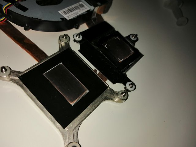
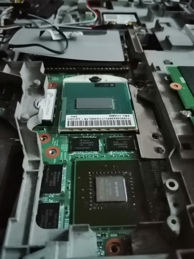
Et voila:

These are the CPU/GPU chips after cleanup with paper towels to remove the excess thermal paste of days past.
Here you can also see that the CPU chip is not soldered onto the board so they can actually be replaced/upgraded quite easily. That said, my chip is the most powerful i7 offered for this model that is still running at 45W. Given that the cooling solution for the i7 Extreme chips is the same as this one I wouldn't want to run a 55W chip at full power in this setting.
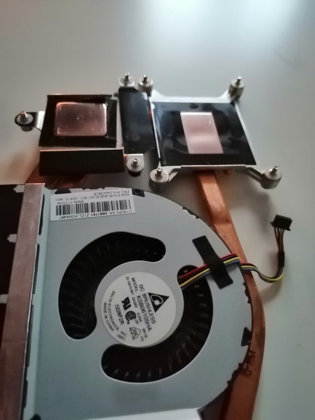
Cleaning and prepping the heatsink
Now that we got the heatsink out we can clean the copper surfaces that sit on top of the chips. The cleaner and smoother this surface is the better it will function. Any air bubbles, scratches or oxidation on the surface will reduce its ability to transfer heat and effectively reduce cooling capability. My surfaces were dull, oxidated and not very smooth:
So what you want to do is simply make the surfaces as clean and smooth as possible by polishing them in a circular motion.
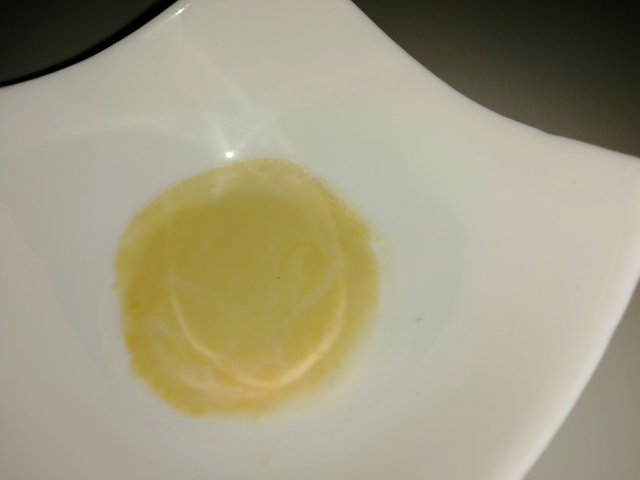
Step 1 Put some copper polish in a dish and add a few drops of alcohol...
Take a paper towel, dip it in some polish and begin the process. In my case it took a full 4 runs until I had removed all the dirt and oxidation. You can easily tell when you're done when the towel no longer shows pitch black residue.
Depending on the aggressiveness of your compound you might remove a fine layer of metal during your cleaning process so we need to even out the surface.
Step 2 Use some pure alcohol on the towel and thoroughly clean the surfaces and surrounding areas of any polish residue and excess dirt. Now put a tiny amount of toothpaste (any will do) onto a clean paper towel and start polishing the surfaces, again in circular motions and clean off with alcohol once you're done.
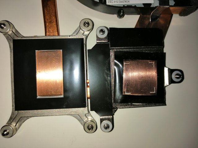
The result should look somewhat like this:
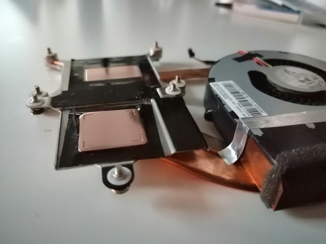
Here in high contrast just to show the smoothness:
That's ready to go to work.
Applying thermal paste and installing the heatsink
What we need now is some killer thermal paste. Do not save money on this as you'll only have to do this once in 3-4 years and the compound is crucial for the correct functioning of the cooling system.
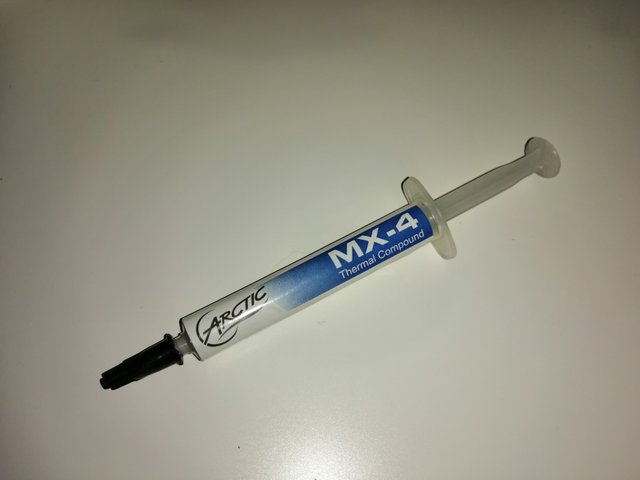
I bought this a few years back when I had thermal issues with my T420s i7 with dedicated graphics. It works great but the "s" chassis T4 series just doesn't have enough room for an effective cooling solution for high performance early gen i7 CPUs but that's a different story.
Go back to your chassis and apply a dot of paste in the middle of the square GPU chip surface and a fine line along the CPU chip surface.
Now we reinsert the heat sink, slide the back end into the chassis below the screen and then wiggle it carefully back and to the left until it snaps into the left side chassis hole. There is no easy way to do this, the only thing to watch out for is that the cables are out of the way and that you don't brush the thermal paste off of the chip surfaces - good luck!.
A good 5 minutes later I was looking at this:

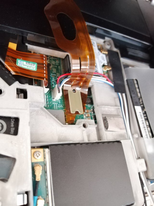
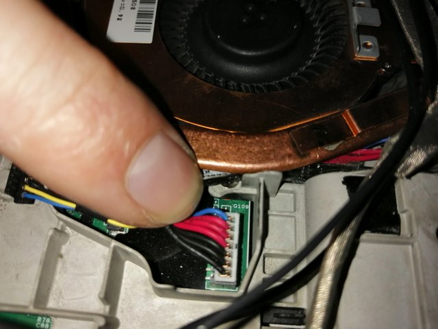
I fixed the screws and was quite happy until I noticed a cable that ran across the sink in a weird fashion:
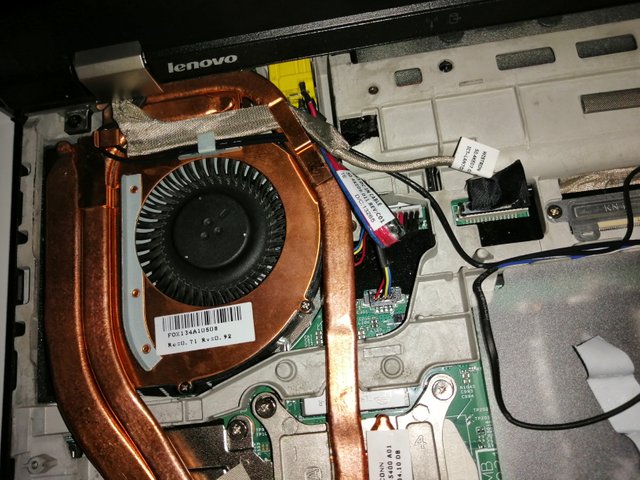
A quick check with my 'before pics' confirmed that the red/blue power cable should run below and not over the heatsink. After a few minutes of procrastinating consideration to leave it like this I decided to pull it again and do it right.
Exactly 20 minutes and few erratic fits later I had it all in place - needless to say this required pulling the heatsink, removing the thermal paste from the chips and heatsink surfaces, reapplying and then reinstalling it - whooohouu.
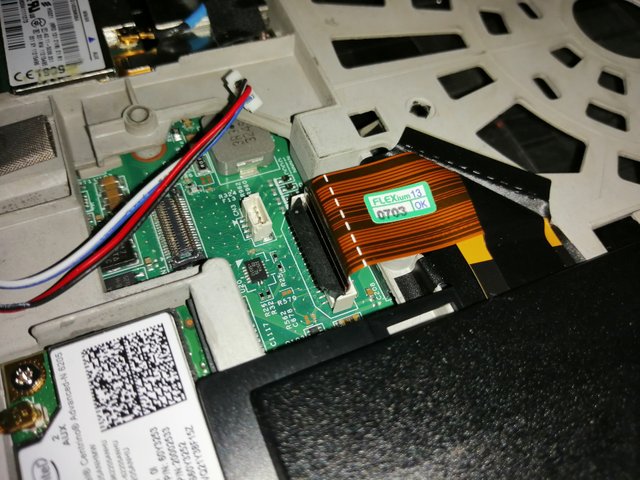
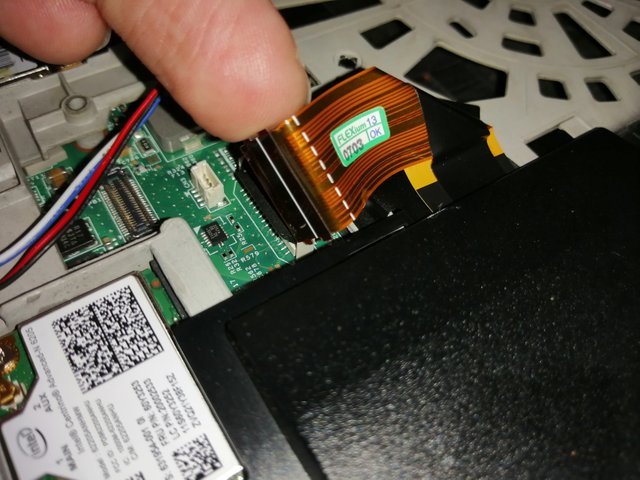
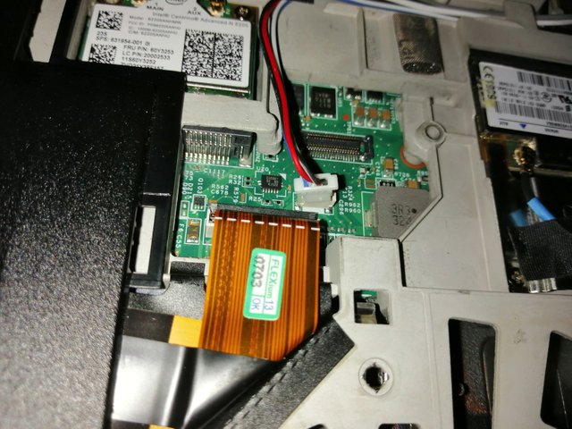
As you can see the power cable now runs under the assembly hence the kink in the cable as it always sat like this. I checked for space:
Then put all the cables and the speaker back in place:
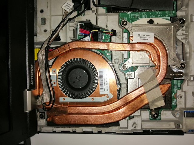
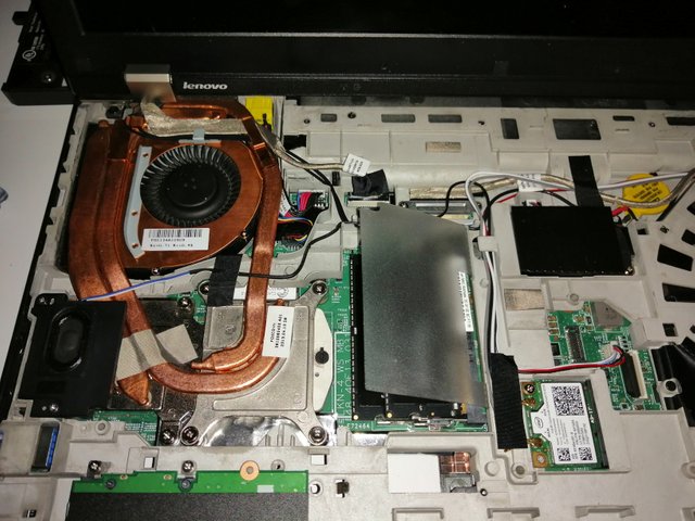
And we're done with the bigly part of it all. I put a new piece of tape in place to arrest some cables and reinserted the palmrest:

Only thing to watch out for when reinstalling it is to slide it in at an angle under the screen so it can correctly hook into the hinges at the back of the chassis. I had to do it twice because they didn't snap in the first time which you'll be able to tell by a gap between the palmest and the chassis at the back near the screen hinges.
Creating some heat
In order to check if all the effort was worth it it was time to fire it up and see if a) it still works and b) if so, are the temps now lower?
The short answer is yes. The long answer is they're much lower like 20C degrees lower.
This test was done with an ambient room temperature of 30C degrees so safe to assume it won't ever get any hotter. Please download the images to take a good look:
Test 1:
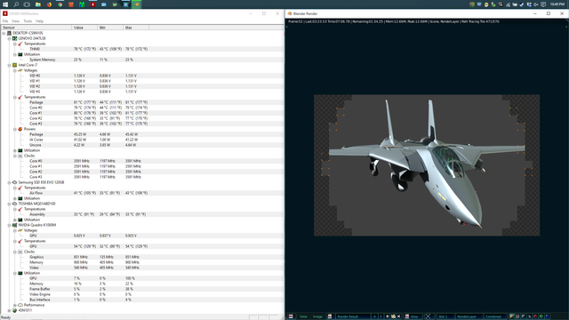
Rendering in Blender using GPU only:
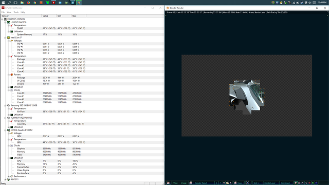
Surprisingly GPU activity hardly influences CPU temps at all. Under sustained load the GPU never rises above 51C degrees and happily maintains its (rather low) clockrate of 850MHZ.
Test 2:
Rendering in Blender using CPU only no AC attached / balanced power mode:
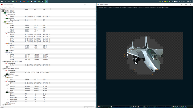
When switching to CPU only temps rise very quickly but level out at around 64C degrees with a sustained clockrate of 2295MHZ. Reason for this low clockrate is that the power management was set to balanced so in that mode on battery power the highest clockrate is jut around 2.3GHZ. Fan was on medium setting and almost unnoticable.
Test 3:
Rendering in Blender using CPU only on AC in unrestricted mode:
Here the temps instantly jump to over 80C and clockrate goes to 3.8GHZ, fan goes to full and the clock quickly starts to throttle down as it levels out. I attached the AC to give it maximum power but even after a few minutes and room temperature of 30C+ degrees temps never rose over 81C and averaged 80C with a sustained clockrate of 3591MHZ or 3.6GHZ - quite impressive and a great improvement:
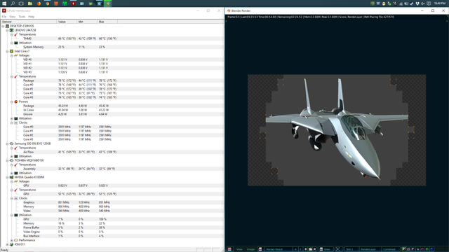
Test 4:
Prime 95 max heat torture test on full power in unrestricted mode:
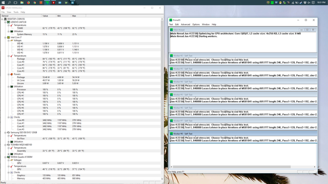

As a final test with the same room temperature I ran the Prime 95 and even here it peaks at 87 (for a second), levels out at around 85 and quickly goes to average out at 83C with clock rates between 3192MHZ and 3292MHZ mind you this test is taxing all cores to their max continuously so it doesn't get worse than this.
Final remarks
As you've seen replacing the thermal paste and cleaning your surfaces does wonders to your computer's thermal management and cooling abilities plus it directly affects performance.
I don't usually use the GPU as it is quite useless so I disabled it in BIOS following this operation and with it powered off the temps go down another few degrees for the CPU.
All in all I started with bad paste and a dirty cooler at avg temps of 99C and peaks of 102C (!) and now sit at avg temps of 83C and peaks of 87C - under full load.
As for idle temps they hover around 50C now with these very high ambient temps and fan is usually off when not under mid to high loads. This was previously around 60C.
Hope you enjoyed this as much as I did putting it together and steem on (on your Thinkpads).
Peace out.