Improvised Gears
I've always been fasinated with gears, and that fascination only increased when I learned how to make them using an involute cutter and dividing head. Gears, of course, are a necessary fashion accessory to every steampunk, myself included (though the ones I wear are all inside my pocket-watch and visible only through a little window)! Anyway, I have mentioned it at some point, or I may not have, but the first CAD program I learned to use was MasterCAM v9.1. I liked it, though it doesn't have the capabilities that Autodesk Inventor does when it comes to making models, and it doesn't export .stl files as cleanly. One thing that MasterCAM does better than Inventor, in my opinion that is, is make gears. Oh, you can make gears in Inventor, but only as assemblies, not as individual involute drawings that can be edited. Furthermore, I've never once gotten the gear function in Inventor to work. However, since I know how to MAKE gears the old-fashioned way, I decided to improvise. Here's a not-very-accurate method of rendering a gear in Autodesk Inventor, but will produce fairly decent results.
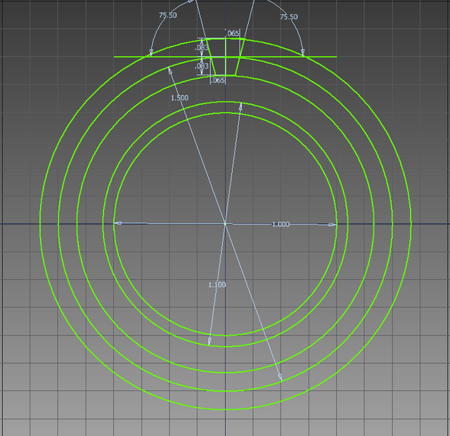
Step 1: draw up the specs
All information can be found in Machinery's Handbook. I usually start with the pitch diameter and go from there. Note that the pressure angle in this drawing is an unusual 14.5 degrees, because reasons.
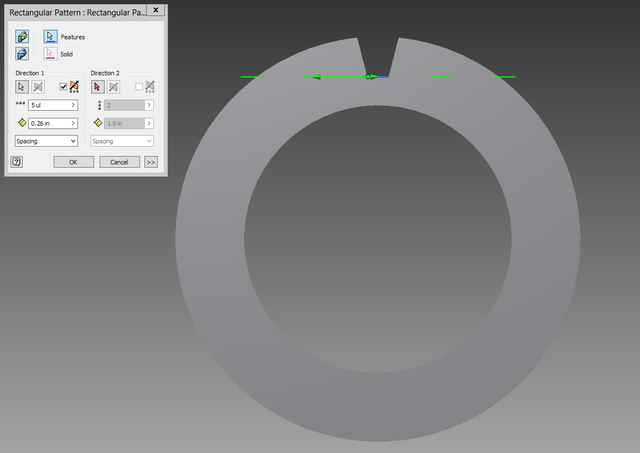
Step 2: extrude the gear blank and first tooth groove SEPARATELY. You'll see why in the next step. What I'm doing here is virtually duplicating a method of machining a gear using a gang of tapered slot cutters rather than an involute cutter. I first saw this in one of my home shop journals.
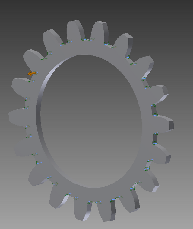
Step 3: create a rectangular pattern of the teeth. Were this pattern on a flat bar, you would have a perfect rack and could call it a day, because that's how that type of gear is made. We're not doing that, however.
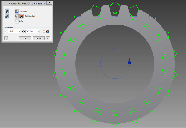
Step 4: create a circular pattern of the rectangular pattern:
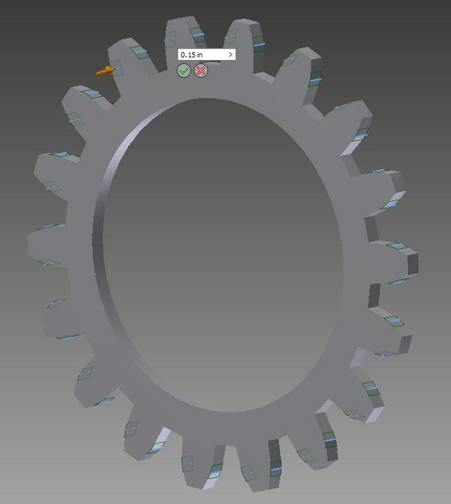
Step 5: clean up the involute curves. There are two fillets you need to put in to do this, and Machinery's Handbook won't be as much help with the value of the first one, since this isn't the proper method to begin with. However, you can still get a decent approximation. Furthermore, if you intend this gear to be functional, then just run some sand between it and its mate and the gears will wear into each other faster. This, by the way, is an actual industrial process for finishing gears. Not making this up.
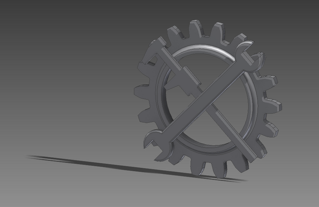
Step 6: add the other features to your gear. If this is to be a functional gear, that would include additional shafts, additional gears, keyseats, keyways, holes, spokes, etc. This particular gear, however, I made into a steampunk badge:
You can see a full 3D view of it by clicking the link below:
https://www.shapeways.com/product/BXCTGXDEE/engineering-corps-badge
I'd go into more detail (basically just copying and pasting the product description from the above link), but my house guest just woke up, and I've already been rude enough.
Most people don't know about involute tooth profiles or CAD/CAM. I have designed gears in AutoCAD and SolidWorks, although I have little direct knowledge of MasterCAM beyond one class. I hated its design tools to be honest, but it was good for tool paths.
I have made some fairly complex designs in MasterCAM, but ever since I discovered Inventor, I prefer using that, and then exporting models to a .step file if I plan on writing toolpaths for them. As far as I know, that's also standard practise in industry.
Yup. Using MasterCam for design is more of an emergency option that can be used.