This tutorial is an open source arduino project that teaches how to make Arduino LDR sensor Laser Tripwire Security Alarm using keyes ky-008 laser module, light sensor module and buzzer this project is very useful for school and indoor activities.
- Gather all the Requirements
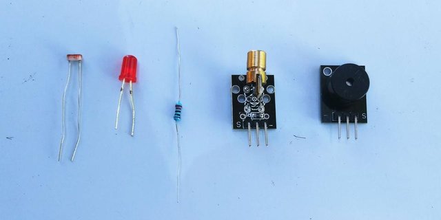
keyes - 008 laser module
piezo buzzer
Light sensor module
resistor
1 Led
2 Breadboard /
jumper wires
Type B usb cable
Arduino UNO R3 board
PC
The LDR or light dependent resistor is device that is able to detect ambient and light intensity, it provides maximum possible contact area with the two metal films, the cadium sulfur track is used as the photoconductor it contains electrons when light is not contacted with it. As soon as light falls on the sensor, the electrons are liberated and the conductivity of the material increases. it has set of 2 legs, the positive leg in no particular position is connected to 22ok ohms resistor.
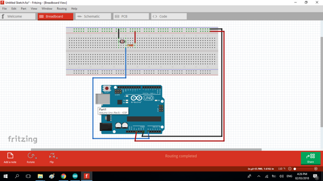
The connection of LDR to arduino
| LDR | ARDUINO |
|---|
| The Black wire attach to LDR other (empty) leg | GND |
| Blue wire attach to LDR and resistor same column | A0 |
| Red wire attach to resistor empty leg | 5V |
The laser ky- 008 module it resistor appears to be related to a control input and it's too high value (10K) to be a simple series resistor this laser we will use the laser 2-wire connections, current control is external, usually in the form of a current-limiting series resistor of small value which is the signal pin and the GND to circulate the current flow on the module.
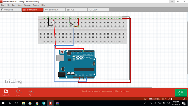
The connection of LASER to arduino
| LASER | ARDUINO |
|---|
| Black wire | GND |
| Sensor wire | D7 |
The LED has 2 sets of leg the short one is the common cathode and the long leg will be the VCC, on this procedure place the led on the breadboard vertical rail or on the middle rail, on the long leg connect the 22ok ohms resistor then to digital pin 12 on the arduino. the long short leg should be conncted to GNd pin. the piezo buzzer is a typo mini speaker that produces beeping sound perfect for alarm ringtone, it converts electric power to produce sound. the short leg of the buzz is the common ground, the long is the vcc.
The connection of LED and BUZZER to arduino
| LED/Buzzer | ARDUINO |
|---|
| Buzzer + | D11 |
| Buzzer - | GND |
| Led + | D12 |
| Led - | GND |
Dowload the arduino Desktop IDE: https://www.arduino.cc/en/Main/Software
When the download is finished, un-zip it and open up the Arduino folder to confirm that click yes, there are some files and sub-folders inside. The file structure is important so don’t be moving any files around unless you really know what you’re doing.
SOURCE CODE
const int ledPin = 12;

const int buzzerPin = 11;

const int ldrPin = A0;

const int laserPin = 7;

void setup () {

Serial.begin(9600);

pinMode(ledPin, OUTPUT);

pinMode(buzzerPin, OUTPUT);

pinMode(ldrPin, INPUT);

pinMode( laserPin , OUTPUT);

digitalWrite( laserPin , HIGH);

}

void loop() {

int ldrStatus = analogRead(ldrPin);

if (ldrStatus < 700) {

tone(buzzerPin, 100);

digitalWrite(ledPin, HIGH);

delay(100);

noTone(buzzerPin);

digitalWrite(ledPin, LOW);

delay(100);

Serial.println(" ALARM ACTIVATED ");

}

else {

noTone(buzzerPin);

digitalWrite(ledPin, LOW);

Serial.println("ALARM DEACTIVATED");

}

Serial.println( ldrStatus );

//delay(10);

}
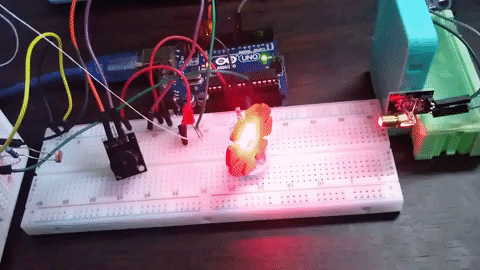
Now, you can see if i remove the object that blocks the laser that passes through the LDR the alarm system should activated and the buzzer starts beeping. if you have important things that need to secure use tripwire laser security alarm.