Kilovolt Drivers, Biased versus unBiased.
Well howdy,
I thought I'd do a short write up on the difference between a biased aka polarized driver, and an unbiased aka non-polarized driver, for what would typically be used to drive a tesla coil or relative potential source.
Most people who play with tesla coils are familiar with the biased driver. The tesla coil generally puts a single capacitor on one side of the primary and the spark gap on the opposing side.
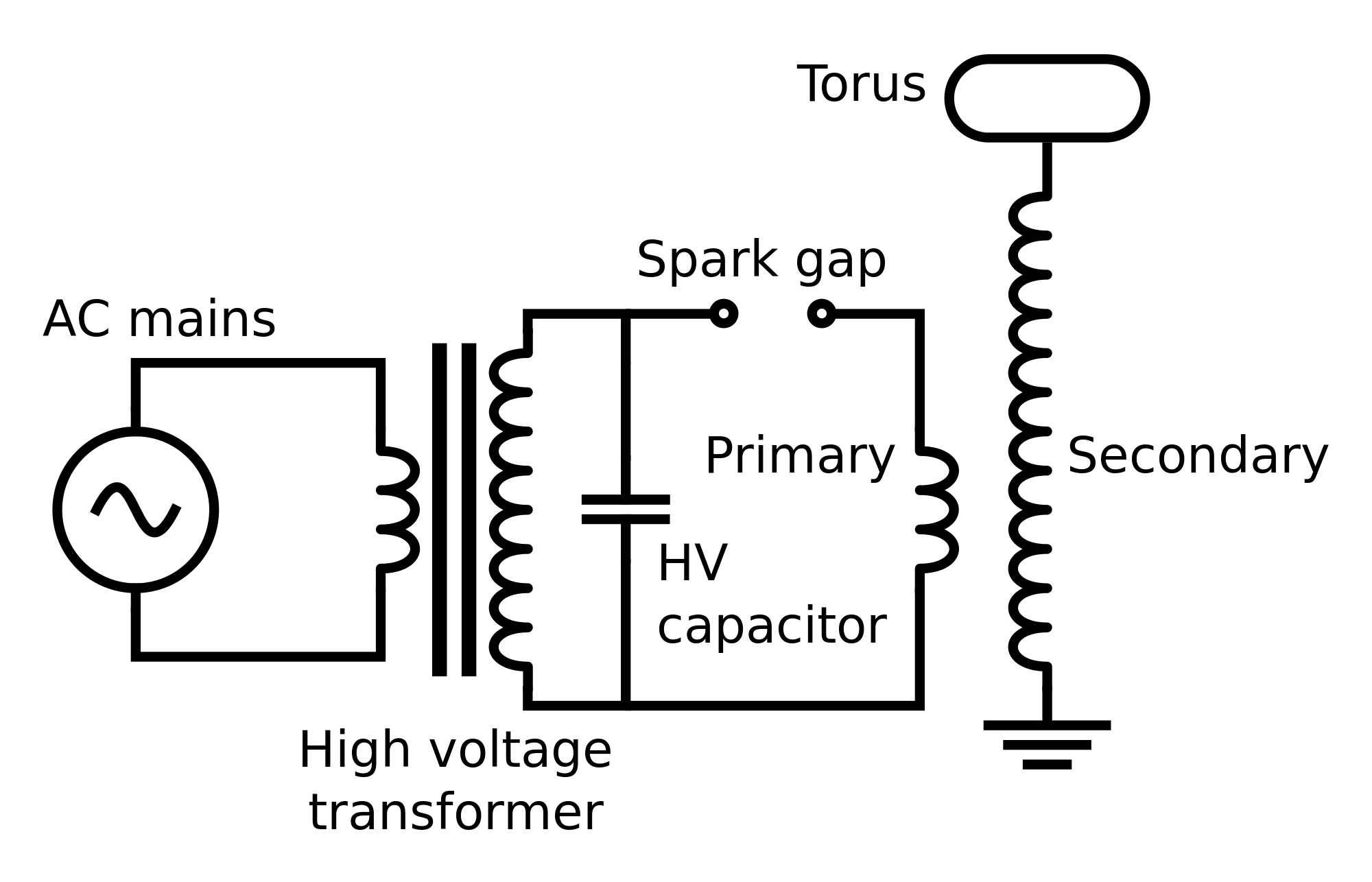
Note the placement of the capacity. In this instance its open to the AC oscillations of the source mains, and the inductances of the secondary output to the cap, and the inductance of the primary tied to one side of the capacitor, means that on the top left of the spark gap you will have a noted measurable polarity present just before it breaks down in the gap. Meaning it can be Positive on the left and negative on the right, to induce breakdown or it can be the inverse, negative on left and positive on right, to still induce breakdown. When it breaks down thats when the powers transmitted thru the primary to ring the secondary. Most people attribute this type of driver as a tesla coil driver.
Not to many people are aware that theres an option for an UNBIASED driver out there that was, as far as I can tell, originated by D'arsonval. This type of driver is setup to make use of DC charging and then has its spark gap setup not in the direct path of the primary but instead it sits behind the capacities that are in series on either end of the primary so that it can Charge up those capacities, without putting a Measurable volt bias over the primary itself. It can charge to whatever KVDC and you will never be able to measure that tension on the primary thats acting as the middle conductor between the two series capacities.
This is why I call it the unbiased driver. Its not seeking to polarize the secondary one way or the other Only, but instead it appears to cause the ambient charge that upholds the secondaries form to aggregate additional charge to itself... sorta like getting the metal wire to take on a static electric charge. I initially started playing with this type of driver on a simple tesla coil mock up I had on the bench and I modified the coil configuration to be 3 coils instead of the typical two. I added a 3rd coil of the same dimensions as the primary over the top half of the Secondary, and I could then short the secondary to itself and the tertiary to itself and run a single wire out from both shorted coils to a spark gap as the output of what I came to call the Bellerian apparatus.
This type of driver appears to cause whatevers placed in its centering output of a primary to take on additional charge to itself of its own polarity... not bias it to become positive or negative... Heres an example of the D'arsonval type driver.
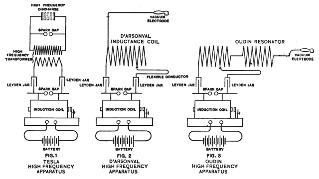
Note the two leyden jars shown on the ends of the primary and where the spark gap is placed in relation to the leyden jars. This is why you can't measure the kvdc volt tension on the primary, even though it is wholly present, it is not Divided, but is instead inflated or maybe compressed/condensed to a higher state of charge without polarity.
Some other things I've found in trying to make use of this type of driver is that the Transformer Core design MATTERS, as this won't work well with EI type laminate cores, but it Does work well with Oil Ignition transformers which use split coils and an O laminate core to adjust the output voltage. Most NST's or alternative power supplies use EI type cores or toroids with single coils, so they don't appear to exhibit the curious pass thru noted with the O split coil configured transformer.
Heres a basic setup one can build to then be able to Play with the different styles of drivers for oneself so one can see and experience the differences first hand. This basically the "bellerian apparatus"
1 x oil ignition transformer (http://www.ebay.com/itm/ALLANSON-2721-630-Oil-Burner-Ignition-Transformer-/331996875451?epid=691458036&hash=item4d4c8e4abb:g:jioAAOSwtfhYtO4R)
2 x 20uF ac run caps (http://www.ebay.com/itm/20-MFD-Motor-Run-Capacitor-370-vac-Volts-AC-Motor-HVAC-20-uf-/272852595829?epid=1740138471&hash=item3f87483475:g:wwEAAOSwL5BZwASA)
1 x mains pigtail (http://www.ebay.com/itm/12Ft-12-Feet-2-Prong-Extra-Long-AC-Wall-Power-Cord-for-Led-Lcd-Tv-Vizio-Samsung-/263036034924?epid=1675082696&hash=item3d3e2b5f6c:g:WUgAAOSwcdBWStnJ)
1 x single on/off switch (http://www.ebay.com/itm/AMBER-20-amp-switch-100vAC-110vAC-115vAC-120vAC-at-20A-max-DPST-on-off-sw-/262839564899?hash=item3d32757a63:g:rdcAAOSwA3dYl~fQ)
4 x hv diodes to take the 10kvac 23mA to DC (http://www.ebay.com/itm/4pcs-100mA-15KV-2CL2FL-High-Voltage-RECTIFIER-Diodes-HVCA-/391885124365?hash=item5b3e2c730d:g:LdEAAOSwrklVLjLv)
2 x primary coil (one for driving, one shorted to self on top of secondary for half of output. Make ur own with 1/4inch soft copper pipe for primaries, and wind a secondary or snag one from the guy on ebay selling Slayer exciter kits. Might wanna get the secondary first then wind the primaries so you know the diameter to make the primaries.)
2 x doorknob caps 1-12nF in rating and good for 16kvdc (I used 2 x 3300pF 16kv glass teflon caps as the plastic doorknob caps kept exploding themselves.) (http://www.ebay.com/itm/3300pF-16kV-teflon-doorknob-capacitors-FGT-I-Lot-of-4-/160700180882?hash=item256a7a2992:g:ba0AAOSwPc9WycGa) [when these caps fail, their capacity increases, fyi]
1 x tesla style secondary (http://www.ebay.com/itm/Mid-Size-Tesla-Coil-Primary-Secondary-Plus-Slayer-Exciter-Circuit-diagrams-/162510221927?hash=item25d65d3267:g:M0UAAOSwTglYk2wS)
The assembled apparatus uses this schematic:
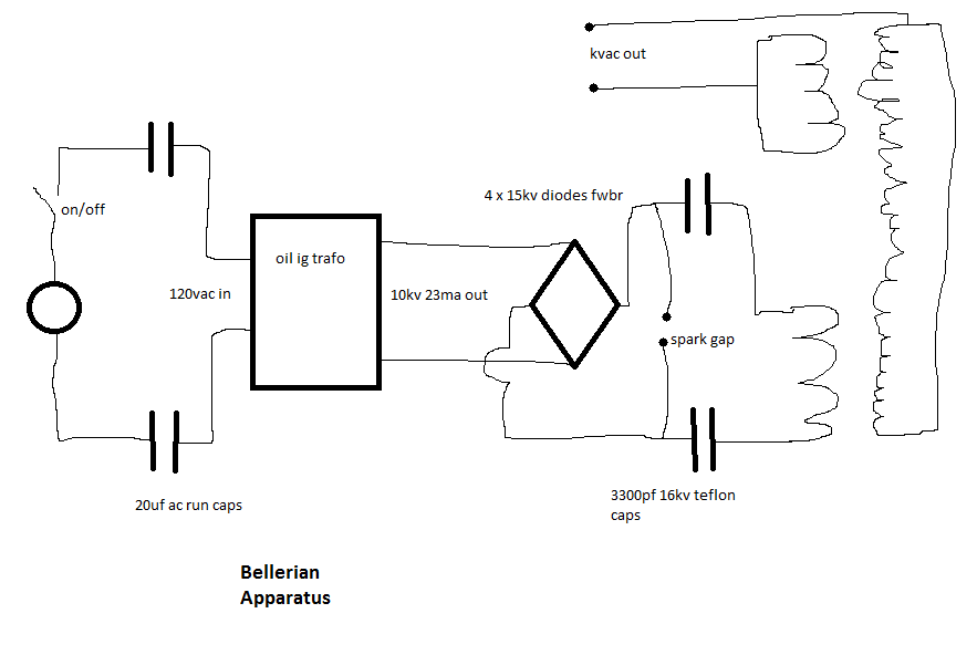
Once its built you can play with how the secondary acts as a sort of waveguide to the tertiary and how whats produced on the primary appears to be produced on the shorted tertiary, which is disparate from the voltage produced on the secondary which was the transmitting medium that caused the tertiary to be affected by its locality to the secondary. Maybe the secondary should be elongated and multiple different turn count coils be put over it and shorted out to themselves to see if the volt disparity between the various "primary" type coils can be drawn from to do work...
Lastly I am open to discuss these things and try to refine a mutual understanding regarding them. These are how I think of these things today, should something else become known I'll have to account for it as well, so its an ongoing exploration...
Hope its helpful!
Gene/Bellerian1
@steemstem