From DC to Dynamic, Testing Bidirectional OBCs with a Dual-Channel Battery Simulator
The humble On-Board Charger (OBC) has undergone a revolution. No longer just a one-way street for AC grid power to flow into the battery, the modern OBC is bidirectional. This unlocks game-changing capabilities like Vehicle-to-Grid (V2G), Vehicle-to-Home (V2H), and Vehicle-to-Load (V2L), transforming EVs from mere consumers of energy into mobile energy storage units.
But with this new functionality comes immense testing complexity. How do you thoroughly validate a system that must efficiently and safely convert power in both directions, interacting with both a high-voltage battery pack and a dynamic AC grid? The answer lies in moving beyond static DC testing to a fully dynamic test environment, and the key instrument enabling this is the Dual-Channel Battery Simulator.
The Testing Challenge: More Than Just Charging
Testing a bidirectional OBC presents a unique set of challenges that traditional power supplies and loads cannot address:
- The "Source" and "Sink" Dilemma: During charging (AC to DC), the OBC draws power. During discharging (DC to AC), it injects power. A test system must seamlessly transition between being a sink and a source for both the AC and DC ports.
- Complex System Interaction: You're not just testing a box in isolation. You need to simulate the real-world behaviors of both the battery (varying voltage, state-of-charge, internal resistance) and the AC grid (voltage sags, swells, frequency shifts).
- Safety and Protection: Bidirectional power flow introduces new failure modes. Robust testing of over-voltage, under-voltage, and anti-islanding protection is critical.
This is where a single-channel simulator falls short. A dual-channel simulator, however, is perfectly architected for this task.
The Dual-Channel Advantage: A Complete Test Bench in One Instrument
Imagine a test setup where you can dynamically control both sides of the OBC simultaneously. A dual-channel battery simulator makes this possible.
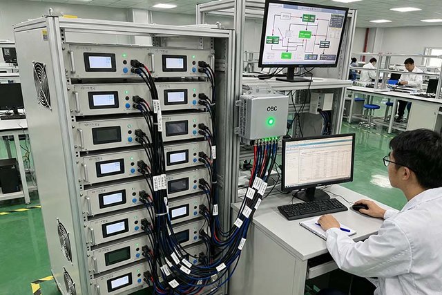
Typical Test Setup
- Channel 1: Connected to the OBC's DC port, simulating the EV Battery Pack.
- Channel 2: Connected to the OBC's AC port (often via a programmable AC source or directly, depending on the simulator's capabilities), simulating the Electrical Grid or a home's AC bus.
With this configuration, you unlock a world of dynamic test scenarios.
Scenario 1: Validating V2G Efficiency and Grid Support
Goal: Test how effectively the OBC can feed power back to the grid and respond to grid commands.
Simulation:
- Channel 1 (Battery Sim): Program a dynamic profile representing a battery at 70% SOC with a specific voltage curve.
- Channel 2 (Grid Sim): C+ommand the OBC to inject a specific amount of real power (e.g., 5 kW) back into the grid. Then, dynamically change the grid frequency (e.g., +0.5 Hz) to verify the OBC reduces its power output as required by grid standards (e.g., IEEE 1547).
Scenario 2: Testing Seamless Mode Transition
Goal: Ensure the OBC can smoothly transition between charging and discharging without fault.
Simulation:
- Start with Channel 2 sourcing power (grid simulating charging) and Channel 1 sinking power (battery simulating charging).
- Issue a command to the OBC to switch to V2G mode.
- Instantly, Channel 1 must seamlessly transition to sourcing power (battery discharging), and Channel 2 must transition to sinking power (grid absorbing energy).
- A high-performance dual-channel simulator will handle this bidirectional power handoff without overshoot or shutdown, revealing any instability in the OBC's control loops.
Scenario 3: Creating Real-World, Corner-Case Conditions
Goal: Stress-test the OBC's protection and operational limits under conditions that are dangerous or impossible to create with real batteries.
Simulation:
- Low SOC Discharge: Set Channel 1 to simulate a battery at 10% SOC with a corresponding low voltage. Then, command a V2H discharge at full power to verify the OBC correctly derates or shuts down before damaging the "battery."
- Grid Fault: Use Channel 2 to simulate a rapid grid voltage sag or swell while the OBC is operating. Monitor the OBC's response to ensure it disconnects safely (anti-islanding) and reconnects properly when the grid is restored.
Key Features Your Dual-Channel Simulator Must Have
When selecting a simulator for bidirectional OBC testing, don't compromise on these capabilities:
.jpg)
- True Bidirectional Power Flow: This is non-negotiable. Both channels must be able to source and sink power with high efficiency.
- High Bandwidth & Fast Slew Rate: The simulator must accurately replicate the dynamic response of a real battery and grid. Slow transient response will mask instability issues in the OBC.
- Precise Channel Synchronization: For mode transitions and system-level tests, the two channels must be perfectly synchronized to simulate real-world interactions without artificial delays.
- Advanced Sequencing & Automation (API): Testing mode transitions and complex profiles requires scripting. A robust API (e.g., SCPI, Python) allows you to automate entire test sequences, ensuring repeatability and reliability.
Conclusion: Powering the Future of EV Technology
Bidirectional charging is a cornerstone of the future energy ecosystem. Ensuring these systems are efficient, safe, and reliable requires a testing methodology that is as dynamic and sophisticated as the technology itself.
By employing a dual-channel battery simulator, engineers can create a virtual proving ground, subjecting bidirectional OBCs to a vast array of real-world and extreme conditions long before a physical prototype ever exists. This not only accelerates development cycles but also builds the foundational reliability needed for consumers and grid operators to trust in the vehicle-to-everything future.