Programming / Flashing Sonoff TH16 Wifi Smart switch.
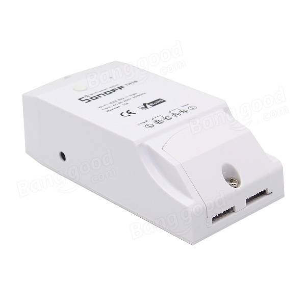
Sonoff is cool little smart switch for not only home automation but for makers and hackers also, why? It’s based on ESP8266 plus it has tx/rx pins accessible and the hardware is well documented (schematics at the end of the post).
Now concerning the Sonoff original software I got it working after around 15 minutes of messing around. For some reason the app also needed my location information, sound recording, access to SD card and so on ….. so yeah not fishy at all. After successful pairing of the switch with app everything worked fine (around 5 minutes) until the app recommended the firmware update….. aaaand its broken. After the update the device was basically just push switch. After the update no matter what I did I could not reconnect the switch to the app.
Luckily I bought it to hack it. So here we go ….
First you need: FDTI USB to TTL adapter. Mine looks following:

1 - Disconnect Sonoff from mains power.
2 - Open the enclosure:
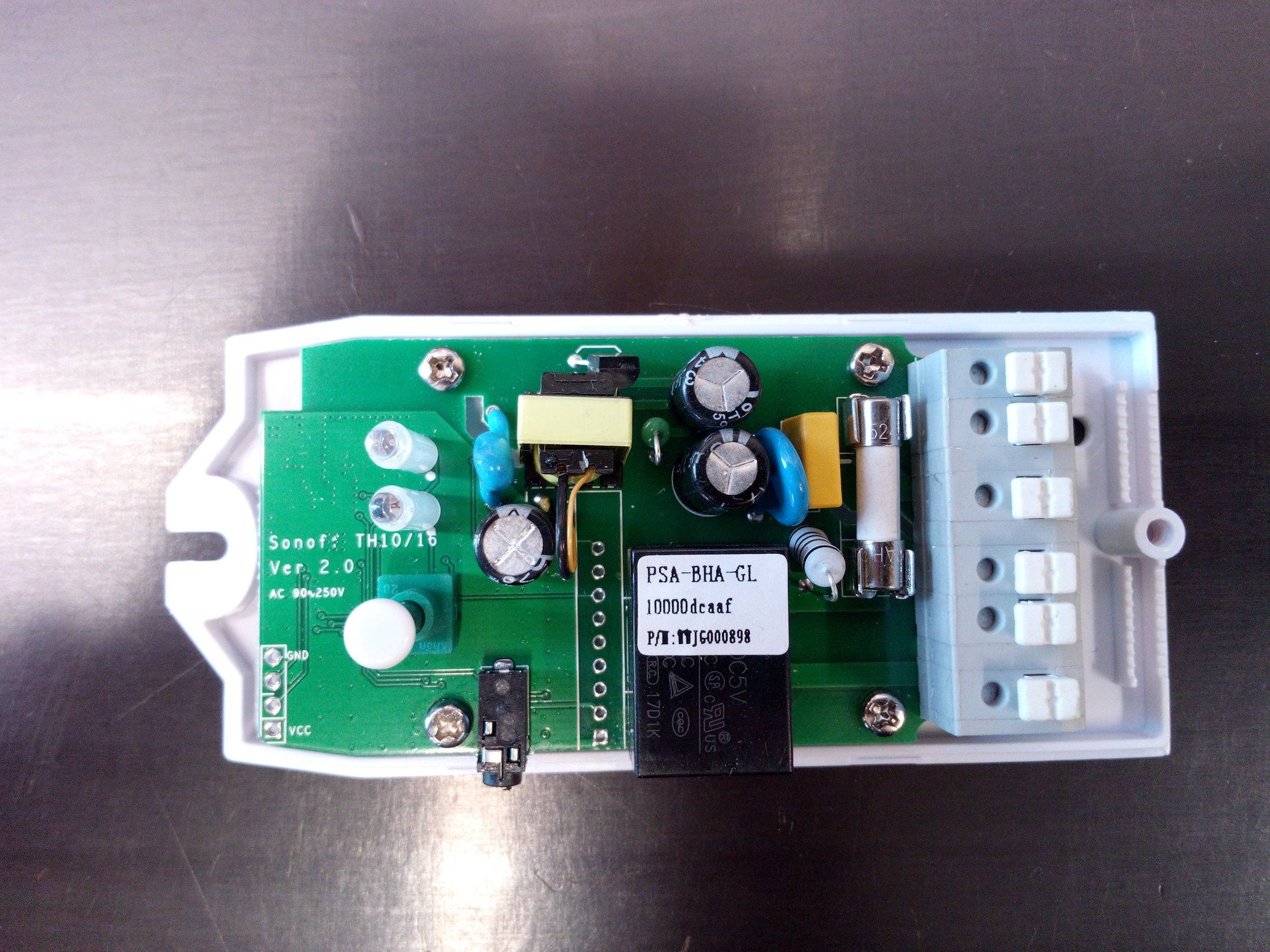
3 - Solder header to PCB:
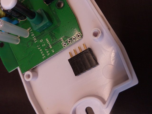
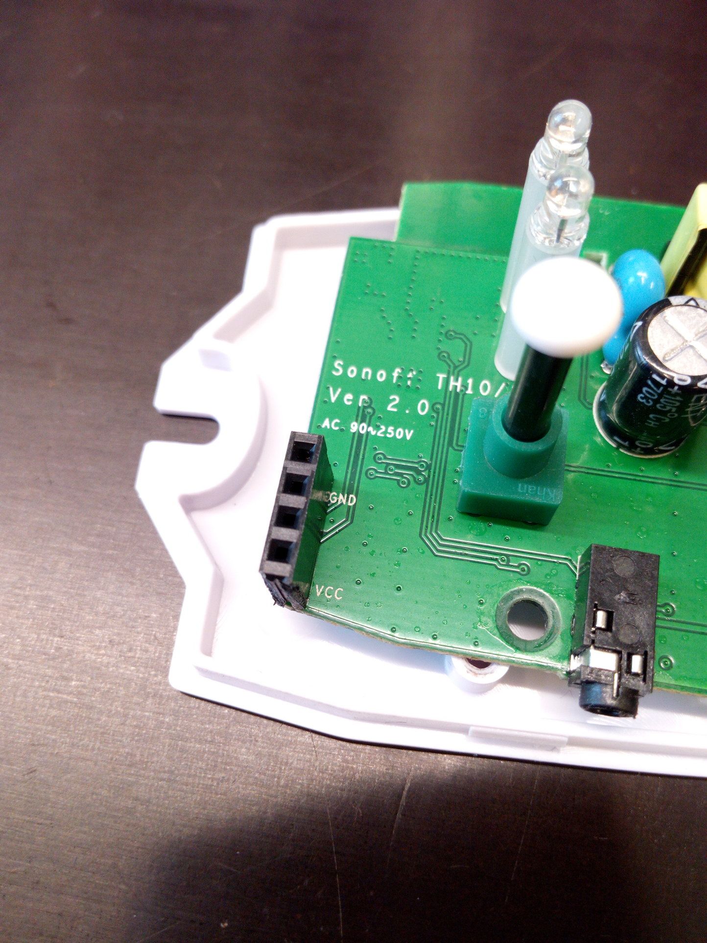
4 - Now connect the FDTI USB to Sonoff. Don’t forget to set your FDTI adapter to 3.3V! On Sonoff only the GND and VCC are marked. Connections are following:
Sonoff -> FDTI
GND -> GND
TX -> RX
RX -> TX
VCC -> VCC
5 - Now before we connect the adapter to computer remember that changes are irreversible. Once you write the changes to Sonoff there is no way to restore the original firmware. In order to enter programming mode you have to hold down the push button while connecting the adapter to computer (and powering up the ESP8266). With this adapter I had to hold down the button only while connecting the usb adapter with computer and after couple of seconds I can release the button and write the program to ESP8266. Now if this does not work try keeping the button down the whole time of connection and program upload.
Another common problem is that FDTI adapter does not supply enough current (With this model of FDTI I did not have that issue). In that case you need to supply 3.3V to ESP8266. (Pins VCC and GND on header).
6 - Now lets open Arduino IDE. How to add the ESP8266 libraries to Arduino IDE I have written before here. Open “Blink” test sketch.
7 - Replace the “LED_BUILTIN” with “13”.
8 - Select “Generic ESP8266 Module” as device and following settings:
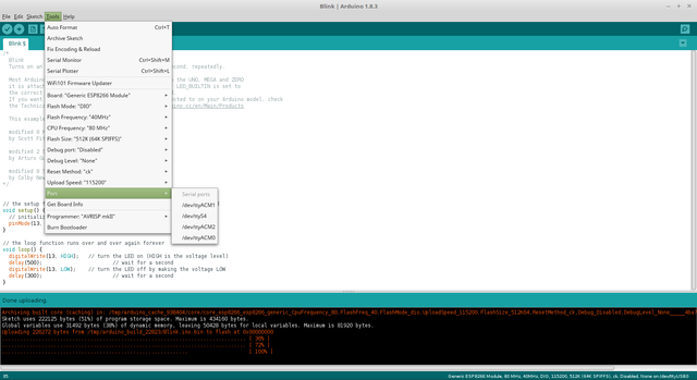
9 - And now Upload sketch. If everything went fine you should see the blue LED flashing after the upload.