IR controlled RF system
Hello everyone!
As an electronics hobbyist i've made a lot of projects using developmentboards like arduino.
Right now i'm working on a home automation system that is able to control devices that use a IR or RF remote.
My main goal is to create a system that uses as few components as possible; is cheap and is very easy to understand and make yourself!
In this post I show how you can start to make such a system yourself. I shows how to get the signals from your RF controlled devices and how to control them using your TV remote control.
For example you could switch your ambiance lighting in your livingroom or control your heating system all with some buttons you did not use on your TV remote.
If you guys like the tutorials I could also make some that show how to control your devices over bluetooth using an android application. Or how to control them via a webserver over your wifi network. And much more!
Okay lets get started. For this tutorial you will need:
- Arduino NANO
- RF 433 Mhz transmitter
- RF 433 Mhz receiver
- IR receiver
- Arduino IDE software and some libraries
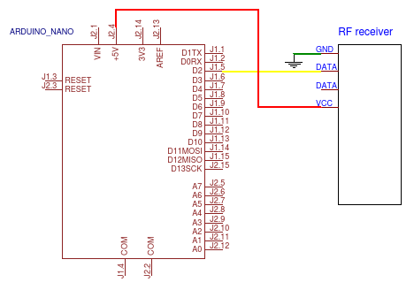
STEP 1:
Wire your arduino nano using the following circuit:
STEP 2:
Copy the following code into your arduino IDE:
/**************************
- Author: diymodules
- Project: RF receiver
- Date: 30-06-2017
**************************/
/***************** NOTES ***********************
- This sourcecode is based on an allready existing code located in example folder of the used library.
- To get te wiring diagram for this project please visit: https://easyeda.com/diymodules/RF_receiver-5d0cb7f2291c4ceb957a61a132ab8082
************** INCLUDED_LIBRARIES **************/
#include <RemoteReceiver.h>
// The library can be downloaded using this link: https://github.com/hjgode/homewatch/tree/master/arduino/libraries/RemoteSwitch
/****************** FUNCTIONS ******************/
void showCode();
/*************** PIN_CONNECTIONS ***************/
// Pin 8 TRG RF-Transmitter
/*************** GLOBAL_VARIABLES **************/
/*************** INITIALISATIONS ***************/
/******************** SETUP ********************/
void setup()
{
Serial.begin(115200);/*
Dont forget to set the baudrate in the lower right corner to 115200 when using serial read/
RemoteReceiver::init(0, 3, showCode);/
RemoteReceiver::init(Pos1, Pos2, Pos3);
In Pos1 the number 0 means that the data pin of the receiver needs to be connected to the first interrupt pin of the arduino.
This interrupt pin is located on pin D1 for the arduino Uno and Nano.
In Pos2 the number 3 indicates that the program will wait until it reads 3 identical signals before it plots the signal on the serial monitor.
This means you may have to hold the button on your remote control a little bit longer before the values appear on the serial monitor.
In Pos3 a function is called named "showCode". In this function the received code and the period of the signal is plotted in the serial monitor.
You have to write both of them down since we need them when making or RF transmit program.*/
}
/****************** MAIN_LOOP ******************/
void loop()
{
// The loop function is left empty...
}
void showCode(unsigned long receivedCode, unsigned int period)
{
Serial.print("Code: ");
Serial.print(receivedCode);
Serial.print(", period duration: ");
Serial.print(period);
Serial.println("us.");
}
Copy the received code and the period duration in for example notepad and save them. You will need them later.
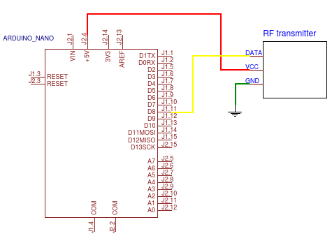
STEP 3:
Wire your arduino nano using the following circuit:
STEP 4:
Now it is time to test if you can control your device with the arduino.
Copy the following code into your arduino IDE:
/**************************
- Author: diymodules
- Project: RF transmitter
- Date: 30-06-2017
**************************/
/***************** NOTES ***********************
- This sourcecode is based on an allready existing code located in example folder the used library.
- To get te wiring diagram for this project please visit: https://easyeda.com/diymodules/RF_receiver-5d0cb7f2291c4ceb957a61a132ab8082
************** INCLUDED_LIBRARIES **************/
#include <RemoteTransmitter.h>
// The library can be downloaded using this link: https://github.com/hjgode/homewatch/tree/master/arduino/libraries/RemoteSwitch
/****************** FUNCTIONS ******************/
/*************** PIN_CONNECTIONS ***************/
// Pin 8 TRG RF-Transmitter
/*************** GLOBAL_VARIABLES **************/
/*************** INITIALISATIONS ***************/
/******************** SETUP ********************/
void setup()
{
//
}
/****************** MAIN_LOOP ******************/
void loop()
{
RemoteTransmitter::sendCode(8, 529980, 189, 3);
delay(5000);
RemoteTransmitter::sendCode(8, 529976, 189, 3);
delay(5000);/*
RemoteTransmitter::sendCode(Pos1, Pos2, Pos3, Pos4);
In Pos1 the number 8 indicates the pin where the data from the RF transmitter is connected to.
The number 8 refers to pin D8 on the arduino NANO.
In Pos2 you need to fill in the code you've written down earlier using the RF receiver program.
In Pos3 you need to fill in the period you've written down earlier using the RF receiver program.
In Pos4 the number 3 indicates how many times the program sends the signal to the receiver.*/
}
STEP 5:
Now it is time to decode the IR signals from your television and look what values you have to use later to switch your devices.
Wire your arduino nano using the following circuit:
STEP 6:
Copy the following code into your arduino IDE:
/**************************
- Author: diymodules
- Project: IR receiver
- Date: 01-07-2017
**************************/
/***************** NOTES ***********************
This sourcecode is based on an allready existing code located in example folder of the used library.
To get te wiring diagram for this project please visit: https://easyeda.com/diymodules/RF_receiver-5d0cb7f2291c4ceb957a61a132ab8082
When using a TV remote it is better to press the buttons in short pulses instead of keeping the button pressed down.
Copy all the signals from the serial monitor and paste them in Excel. Plot a graph and look for repetetive pulses of the same value.
Plot multiple lines in the graph with signals from different buttons on your TV remote and make sure you dont use a value that is also used by another button.
************** INCLUDED_LIBRARIES **************/
#include <IRremote.h>
// The library can be downloaded using this link: https://github.com/z3t0/Arduino-IRremote
/****************** FUNCTIONS ******************/
/*************** PIN_CONNECTIONS ***************/
int RECV_PIN = 11; // Pin D11
/*************** GLOBAL_VARIABLES **************/
decode_results results;
/*************** INITIALISATIONS ***************/
IRrecv irrecv(RECV_PIN);
/******************** SETUP ********************/
void setup()
{
Serial.begin(9600);
// Dont forget to set the baudrate in the lower right corner to 9600 when using serial read
irrecv.enableIRIn();
}
/****************** MAIN_LOOP ******************/
void loop()
{
if (irrecv.decode(&results))
{
unsigned int value = results.value;
Serial.println(value);
irrecv.resume(); // Receive the next value
}
delay(100);
}
Make sure you plot the received signals of multiple buttons in your Excel graph. Television remotes use signals that are very much allike. It is the goal that you search for an repeating signal in the graph that is not accuring in the other buttons.
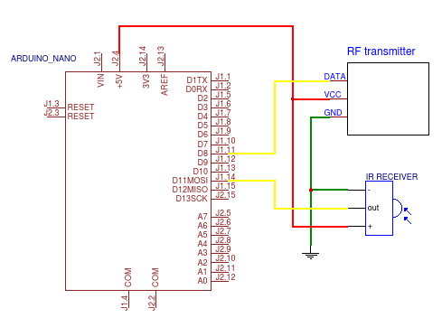
STEP 7:
Now with all the preparations done it is time to make the final system.
Wire your arduino nano using the following circuit:
STEP 8:
Copy the following code into your arduino IDE:
/**************************
- Author: diymodules
- Project: IR controlled RF system
- Date: 01-07-2017
**************************/
/***************** NOTES ***********************
- To get te wiring diagram for this project please visit: https://easyeda.com/diymodules/RF_receiver-5d0cb7f2291c4ceb957a61a132ab8082
************** INCLUDED_LIBRARIES **************/
#include <IRremote.h> // This library can be downloaded using this link: https://github.com/z3t0/Arduino-IRremote
#include <RemoteReceiver.h> // Receiver and transmitter library can be downloaded using this link: https://github.com/hjgode/homewatch/tree/master/arduino/libraries/RemoteSwitch
#include <RemoteTransmitter.h>
/****************** FUNCTIONS ******************/
/*************** PIN_CONNECTIONS ***************/
int RECV_PIN = 11; // Pin D11
// TRANSMITTER is connected to Pin D8
/*************** GLOBAL_VARIABLES **************/
decode_results results;
// You can add and remove codes to the switch case statement. Ofcourse you have to fill in your own values behind "code1" etc..
// #define code1 36465
// #define code2 20145
/*************** INITIALISATIONS ***************/
IRrecv irrecv(RECV_PIN);
/******************** SETUP ********************/
void setup()
{
Serial.begin(9600);
// Dont forget to set the baudrate in the lower right corner to 9600 when using serial read
irrecv.enableIRIn();
}
/****************** MAIN_LOOP ******************/
void loop()
{
if (irrecv.decode(&results))
{
unsigned int value = results.value;
switch (value)
{
  case code1:
    RemoteTransmitter::sendCode(8, 529980, 189, 3);
    delay(100);
    Serial.println("ON");
    break;

  case code2:
    RemoteTransmitter::sendCode(8, 529976, 189, 3);
    delay(100);
    Serial.println("OFF");
    break;
}
irrecv.resume(); // Receive the next value
}
}
And now your system is complete!
I hope you liked this tutorial. It was my first one ever so its propably not perfect.
In this link you can find an overview of all the wiring diagrams used in this project: https://easyeda.com/diymodules/RF_receiver-5d0cb7f2291c4ceb957a61a132ab8082
If you have any questions or remarks about this project please write down an comment below. Maybe if you guys like it I could make a video about the making of this project to make it easier to understand.
Congratulations @coinboi! You have completed some achievement on Steemit and have been rewarded with new badge(s) :
Click on any badge to view your own Board of Honnor on SteemitBoard.
For more information about SteemitBoard, click here
If you no longer want to receive notifications, reply to this comment with the word
STOPBy upvoting this notification, you can help all Steemit users. Learn how here!
Congratulations @coinboi! You received a personal award!
You can view your badges on your Steem Board and compare to others on the Steem Ranking
Vote for @Steemitboard as a witness to get one more award and increased upvotes!
Interesting thoughts