Challenges and Solutions in Testing Electric Drive Systems for New Energy Vehicles
Using ordinary power supplies (typically standard industrial programmable DC power supplies or laboratory power supplies) to test the electric drive systems (motor + inverter + reducer) of new energy vehicles faces a series of fundamental limitations. These limitations can lead to inaccurate testing, failure to conduct tests, or even equipment damage.
Challenges
1. Severe Insufficient Power and Current Capacity
Huge Peak Power Gap: A typical electric drive system boasts power outputs exceeding 100kW, with peak power reaching 200-300kW. Ordinary laboratory power supplies, however, typically operate at tens of kilowatts, making it impossible to provide such massive power.
Inability to Meet Instantaneous Current Requirements: During motor startup, acceleration, or sudden load changes, the inverter requires an extremely large instantaneous current (up to hundreds or even thousands of amperes). The current output capability of ordinary power supplies is negligible in comparison, causing the power supply to enter current-limiting or overload protection states, making testing impossible.
Result: The actual operating conditions of the electric drive system cannot be simulated, especially under high load and high dynamic conditions.
2. Lack of Energy Recovery (Regeneration) Capability
A key characteristic of electric drive systems in new energy vehicles is regenerative braking, where the motor acts as a generator to charge the battery.
Ordinary power supplies are "unidirectional": they can only output energy, not absorb it.
Testing Risk: When the electric drive system is in generator mode, it generates reverse current, which flows into the ordinary power supply. Most ordinary power supplies cannot handle this reverse energy, potentially triggering overvoltage protection shutdown or even permanently damaging the internal circuitry.
Result: No energy recovery-related tests can be performed; test conditions are incomplete, and there is a high risk of equipment damage.
3. Slow Dynamic Response Speed
The inverter in the electric drive system operates using high-frequency PWM (Pulse Width Modulation), with switching frequencies exceeding 10kHz. This means that the DC demand fluctuates rapidly and drastically.
Ordinary Power Susceptibility: The feedback loop and output capacitor design of ordinary power supplies are intended to provide stable, clean DC power; their response speed (typically in milliseconds) is far inferior to the microsecond-level current changes required by the electric drive system.
Impact: This can cause a significant drop or overshoot in the DC bus voltage, making it impossible to maintain stability. This not only distorts test results but may also trigger the undervoltage or overvoltage protection of the electric drive system itself, leading to test interruption.
Result: It cannot accurately simulate the transient characteristics of a battery in a real vehicle, rendering dynamic performance tests invalid.
4. Output Characteristics Mismatch with Real Batteries
Batteries are not ideal voltage sources; they have unique output characteristics.
Internal Resistance Characteristics: Batteries have internal resistance, and their terminal voltage decreases as the load current increases. Ordinary power supplies in constant voltage mode strive to maintain a constant voltage, which does not match the actual behavior of batteries.
Test Bias: Data such as system efficiency and performance boundaries obtained using ideal voltage sources deviate from actual vehicle conditions and are not accurate enough.
Result: Test data cannot accurately reflect the performance of the electric drive system in a real vehicle environment.
5. Cost and Reliability Issues
While a single high-power ordinary power supply may be cheaper than professional testing equipment, multiple power supplies often need to be used in parallel to achieve sufficient power, which increases system complexity and cost. More importantly, forcing a power supply under incompatible conditions will significantly reduce its reliability and shorten its lifespan.
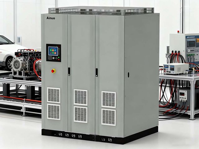
What is a professional solution?
To address these limitations, the industry commonly uses "battery simulators" or "feedback grid simulators."
.jpg)
These professional devices have the following key characteristics:
Bidirectional energy flow: They can act as a source to power the electric drive system and as a sink to absorb energy fed back from the electric drive system, feeding it back to the grid, resulting in energy savings and high efficiency.
High power and high dynamic response: Designed specifically for power electronics testing, with power reaching megawatt levels and extremely fast dynamic response (<100μs), accurately simulating transient battery conditions and DC bus voltage fluctuations.
Simulated battery characteristics: Programmable to simulate battery V-I (voltage-current) curves at different SOC (state of charge) and temperatures, making the testing environment closer to reality.
In Summary
Testing the electric drive system of a new energy vehicle using a conventional power supply is like testing a car headlight with a single AA battery—although both provide power in principle, there are orders of magnitude differences in power, energy flow, and dynamic performance, making it completely unsuitable for core testing requirements and extremely risky. For the development and verification of electric drive systems, a professional bidirectional DC power supply/battery simulator is an indispensable testing tool.