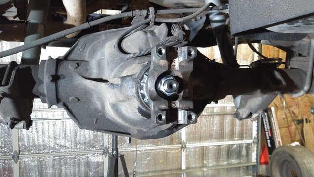
Getting My Rear End in Gear - Part 3 (Final)
Whew! That was a long one. Last I left off with Part 2 I was having a bit of trouble getting the gears in the rear end set up. A lot of it had to do with being worn out from the day with my judgement being questionable, so a new day was born and I went after this problem once more. Now the problem that I was having was that the wear pattern was centered heel to toe on the gear teeth, but the patterns were towards the top of the gear. This meant to me that the pinion depth was correct but that I needed to take out some backlash by moving the ring gear closer to the pinion. Simple, right?
Not so much when I started searching the literature. It seems that the conventional wisdom here is that when anything is off on this style rear end, adjust the pinion depth only to get the desired result. I saw why later on when I tried changing the carrier shims, but this is only a band-aid, and I was chasing my tail for a bit here trying to follow their instructions.
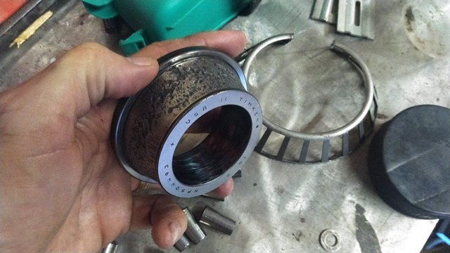
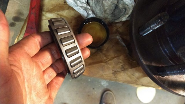
So this is how I started anew. I took the old pinion bearing that I had set up to be slip fit off, then I went to press the new one on, assuming that the old bearing was worn to the point that it effected pinion depth. When I did so, however, I couldn't press it without damaging the cage that the bearing rollers go in. This is the point at which I sacrificed the old bearing to use as an arbor during the pressing operation. When I cut its cage off, I found this on the race underneath. This sort of explains a lot of the metal flake I found in the housing. I imagine the other bearing race looks like this on the inside too, and they were definitely messing with pinion depth readings, so I'm really glad I decided to do this at this point.
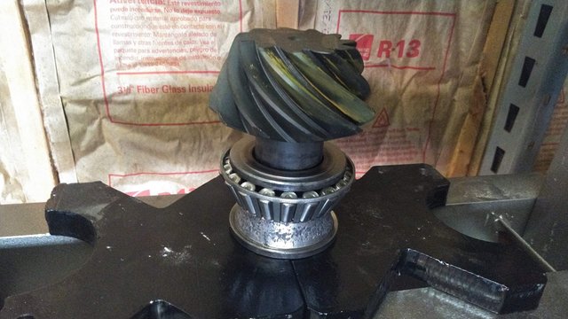
Here it is being pressed on. This setup worked really well and there ended up being no damage to the new bearing as a result. I removed the extra shim and returned to just the factory one to start over.
As you can see here, due to a shoulder being machined into the pinion, there's enough gap in there to slip the bearing separator under the race when pressing off. This ensures that the bearing can be pressed back off too without damage to the roller cage, so my assumption there was correct too. If you have a press and a bearing separator handy, don't bother with the "setup bearings" slip fit thing. It's a waste of time unless you're using brand new bearings, in which case, why not just get a bearing separator with the money instead? But I digress, on to the setup.
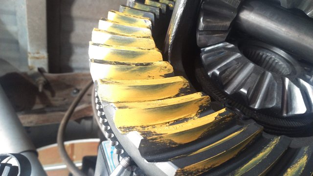
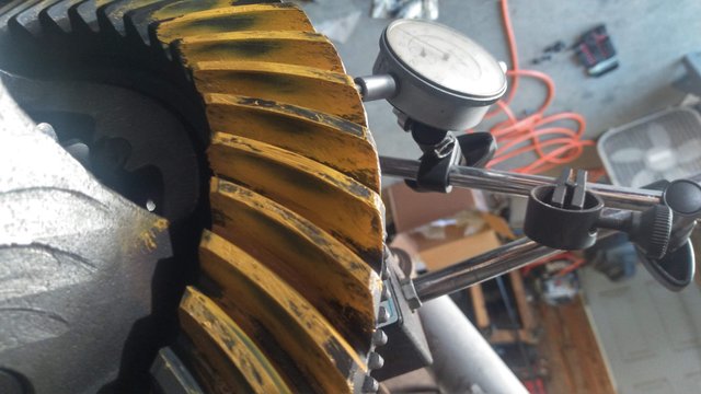
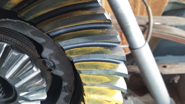
Putting the carrier into place was a lot easier this time. It didn't seem like as much of a workout because I was developing a technique and some muscle memory. This is what the pattern looked like, which isn't bad except the drive side is toe-biased a bit and the wear is toward the top of the gear.
I checked the backlash and it was technically within spec, but at 0.015", it was at the very upper limit, and on a brand new set of gears left no room for wear in. This is where I started looking at references, all which told me to add shims to the pinion in this scenario, so I went down that rabbit hole.
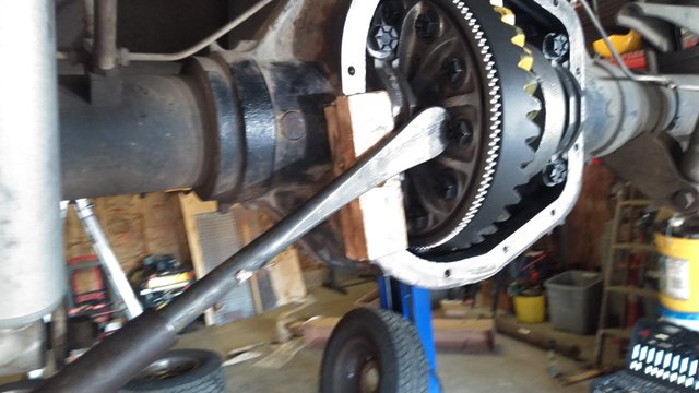
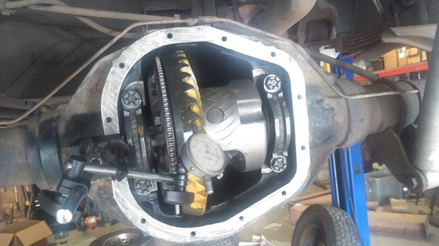
Part of my technique developing. I countersunk, drilled and screwed these blocks of wood to the case so that I could pry the carrier out using a tire spoon and a cheater bar without damaging anything. Kind of crude, but this worked quite well actually, and I found that I only had to pry from this one side to get the whole assembly to pop out.
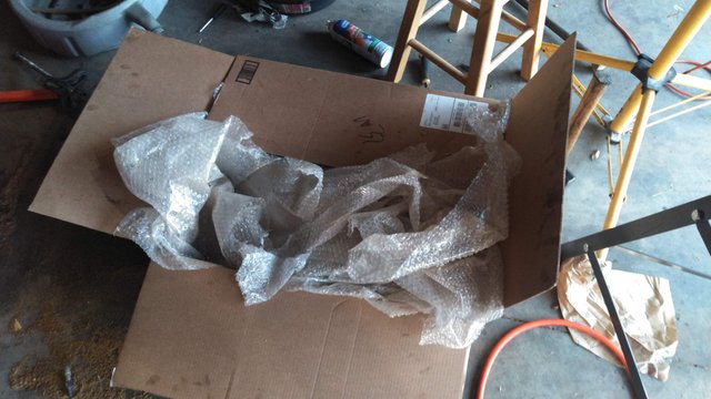
Another crude addition to the technique to save my back a bit. I put this box full of packing materials below the work area just in case the carrier fell out after removing the bearing caps. This way I didn't have to stay with it and I could take my hands off to set tools down and grab others. This didn't end up being necessary for the carrier, but it did save me on the pinion one time, because when I drove it out it popped clean out of the case and safely onto this fluffy bed.
And so it went, press off bearing, add shims, press on bearing, install pinion, install carrier, check, then repeat another time. I kept going with this until my backlash was reading about 0.012-0.013", which I was happy with (range is 0.008-0.015", with 0.012-0.015 being preferred), except that the drive pattern was just about off the toe of the gear as you can see above. This is not the last setup either, it got worse than this by the end. I was not happy at this point, at all. This took a very long time to get here as you can imagine, and while they say this type of pattern is acceptable in the manuals and good for "competition", they tend to be noisy when setup like this, which would drive me crazy. So I started all over again with the actual carrier shims like my instincts originally told me.
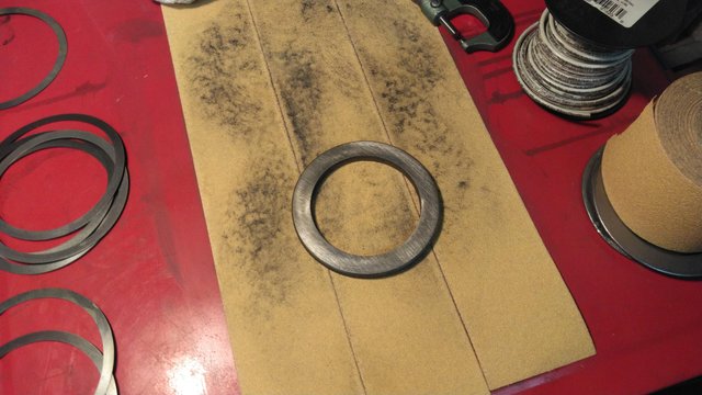
The original shims are like the one above on the sandpaper, one piece on either side of the appropriate thickness, which is driven into the case with a driver and a hammer. You see those thinner shims sitting there on the left? I tried stacking those to the appropriate thickness and using the same technique, but it was impossible. The factory shims are cast material, and these shims are a soft metal, so they just bent all to hell when I tried to gingerly tap them into place while prying on the carrier to create preload on the other side.
I forgot to take pictures of some of this stuff at this point because I was so frustrated, but ultimately I was able to make what I had work. I ended up lapping the shim I wanted to take 0.010" off of it (this is the smallest shim in the kit, so I started there) on some 80 grit sandpaper. I used the flattest thing I had in the shop to glue it to and start grinding the thing down by hand, which sadly at this point is the sheet metal top to the parts washer. By running the piece around in a figure eight pattern and rotating and flipping it over periodically however, you can get very flat and very true (same thickness all over) results even with a semi-flat surface. After over an hour of lapping, I got my 0.010" thickness reduction, it was true within half a thousandth all the way around, and now I could finally do the install.
Now when I was installing the carrier before using both factory shims only, I would install with both shims simultaneously and kind of walk it into the case with a block of wood and a hammer, side to side until it was seated into place. This time, I had to add one of those soft 0.010" shims on the left side, so I installed with just that shim and the factory left side shim first, then drove my modified shim into place with the carrier already seated. This worked beautifully and it ended up actually being easier than the original technique. This first check was with the pinion reverted back to the factory shim once more, and it ended up being about 0.009" backlash with a toe biased pattern, which would be okay, but I wanted to be closer to that "ideal" range of 0.012-0.015" and so I pulled everything apart and removed about 0.005" of shim from the pinion to pull it away from the center of the axis a bit.
This put me at about 0.011-0.012" of backlash, the pattern was more centered, although slightly toe biased, which is about as perfect as I can hope for given the way these differentials are set up. Again, I didn't get a pic, but I remember that the pattern still looked a bit high on the gear, but with the backlash being where it's spec'd for, I'm not too worried about it at this point. Now it was time for final assembly.
With the carrier removed and the pinion driven out, it was time to put on the crush sleeve. I had done this so many times at this point that it went really quickly. Maybe 2-3 minutes to pull the carrier and pinion out. Here it is with a fresh crush sleeve. If you ever do this, I highly recommend getting a second crush sleeve in case you screw up the following step. It's very easy to overdo the torque on this and have too much preload on the bearings.
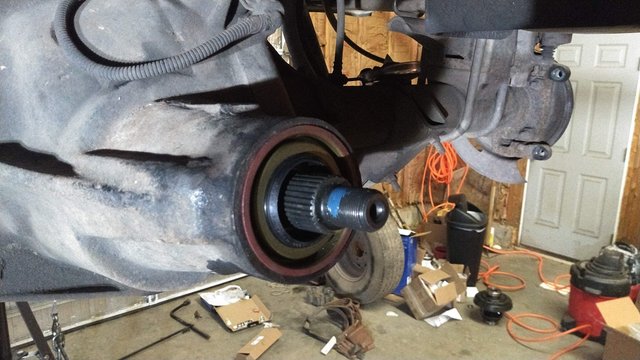
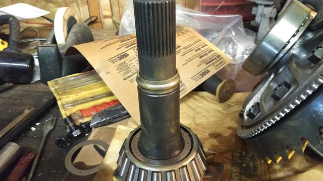
Here's the pinion installed with the crush sleeve, oil slinger and seal. To avoid damage to the seal, I first cinched down the crush sleeve until there was no play with just the driveshaft yoke installed. I then pulled that off, installed the oil slinger and this seal, then added Loctite to the threads for the very final torque sequence. The nut on this is a jam nut designed not to back off, but it never hurts to add a little insurance to something that sees so much vibration.
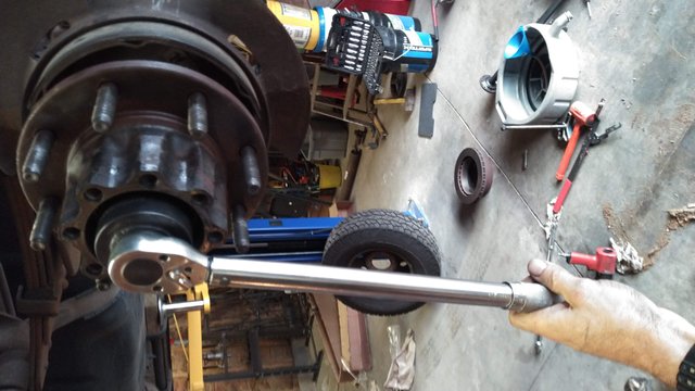
Here's the technique on this. First you tighten down the nut until there's no play in the bearings (you can't wiggle the pinion in and out). This requires either a very long lever or a very powerful ugga dugga wrench (in the immortal words of ChrisFix, also known as an impact wrench lol). In my case, I used an ugga dugga wrench with enough power, but my little pancake compressor only allowed a few ugga duggas at a time, so it took a while to get it to this point. Next, you check the amount of torque required to spin the pinion with either a swing arm or dial style of inch-pound torque wrench. You cannot use a click style torque wrench to do this step. That will only measure the static friction required to get the pinion spinning, not the amount of kinetic friction to keep it spinning. Usually it starts out at less than 5 in-lb. and will very quickly climb from there, so baby steps. At this point, it was as quickly as I could get on and off the trigger. The first shot it climbed to about 14 in-lb, just under the spec'd 16-29. The second shot gave me about 22 in-lb, which is about as perfect as I could hope for.
With the final install done here, it put the carrier back in with the tested-good shims and torqued the bearing caps down to 88 lb-ft. Once more, to ensure nothing was binding before proceeding, I checked the torque required to spin the pinion, which only climbed 10 in-lb. Perfect.
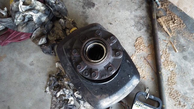
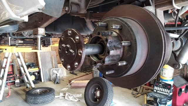
Since I'm in here and spending all this money anyway, I thought it best to redo the wheel bearings and seals as well. With all of this being contained in these hubs, this assembly can be done on the work bench, which is nice.
I drove out the old bearings and seals, then drove in new races. This part was relatively easy, except that I damaged one of the oil slingers that goes on the inside bearing of each hub. Apparently it's there to keep the seal that's on the inside of the hub from being constantly bathed in gear oil, which will cause it to start leaking. I'm just running one wheel without that part for now because you can't get these anywhere but special order or from a dealer, which were all closed yesterday when I did this. I'll pop the new one in along with a new seal when that one comes in the mail.
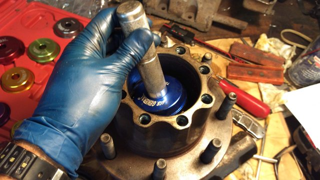
Next was to put the new seal on the inside of the hub. I took a picture of this but for some reason my phone didn't save it for some reason. I had a hard time trying to start this one into the hub with a hammer, which is my usual mode of installing these, so I opted to put it into the press and squeeze it into the hub, being careful not to put to much pressure on it and damage the seal.
I then coated all the bearings in assembly lube, which was just some cheap gear oil I had in the shop already. This is just to protect the bearings from damage during assembly.
Here I was torquing everything down onto the hub. The procedure here is to torque to 60 ft-lbs, and for new bearings like I'm running, back the nut off seven clicks (five clicks for used bearings). This properly sets the preload for the hubs. I wish the differential housing had a setup like this! So much easier than a crush sleeve and shims.
Last thing to do was install of the axle shafts and diff cover before filling the housing with gear oil. I learned this tip from Fordtechmakuloco YouTube channel. When filling a rear end housing, do a proper fill, then install the plug and let it equilibrate for about ten minutes before taking out the fill plug and topping off again. This will allow all of the oil to make its way into the voids of the outer hubs and bearings, which will tend to lower the level from where you filled it, especially with everything dry like with this full rebuild.
After all of that and installing the brakes, driveshaft and wheels, I took it down off the lift and started it up for the test drive. When I first pulled the truck out of the shop and made a sharp turn the rear end made a loud clicking noise almost like a ratchet, which is normal for the initial break-in for a clutch type limited slip or posi differential. It sort of feels like a race car with a mini spool in place of the spider gears. This ratcheting around corners continued for the first 15 miles or so but has since smoothed out. I took it for short repeated test drives over the next 24 hours, letting the diff cool between each run. This is the proper break-in procedure, and I'm supposed to take it easy for the next 500 miles and then change the oil before putting it into severe duty use. I also checked it each time with a laser thermometer and it's running nice and cool. It makes no noticeable noise running down the road, and best of all, I haven't noticed any diminishment in acceleration. In fact, other than right off the line it seems like the truck accelerates a bit harder because it's not shifting as much at such low speeds.
Nice thing about these trucks is that the speedometer runs off of a tone ring and sensor in the rear end housing, so regardless of the gear ratio, it will always spin at the same speed. The only thing that will throw this off is changing the tire size, so I didn't have to make any adjustments or program the computer to make the speedometer work properly. I'm just glad to be done setting up the gears on that rear end and hopefully never having to do that again. Now I just have to remember not to put it in four wheel drive until I change the gears in the front end! Until then, Steem On!
@randr10, you did a great job!
@tipu curate
Upvoted 👌
Congratulations! Your post has been selected as a daily Steemit truffle! It is listed on rank 1 of all contributions awarded today. You can find the TOP DAILY TRUFFLE PICKS HERE.
I upvoted your contribution because to my mind your post is at least 5 SBD worth and should receive 214 votes. It's now up to the lovely Steemit community to make this come true.
I am
TrufflePig, an Artificial Intelligence Bot that helps minnows and content curators using Machine Learning. If you are curious how I select content, you can find an explanation here!Have a nice day and sincerely yours,

TrufflePig