Logic Design - VHDL Sequential Circuits
Hey it's me again drifter1! Today we will get into VHDL Sequential Circuit Programming. You can find the Theory here if you want to remember things or just got started! I will today talk about how we write a DFF, 4 Types of Registers and Counters! We will also talk about different Signals/Inputs that we use to do do things Asynchronous and Synchronous like Reset Signals! So, let's get started!
Quick Reminders:
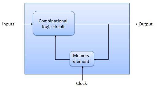
To give you a smooth transition we will first start out with things that you already know! A Sequential Circuit uses Combinational Logic and Memory Elements. Memory Elements are things like Latches or Flip Flops that change Output depending on Input and also during a specific Clock event. Such a Memory Element can be Level or Edge Sensitive as you might remember from Theory. We can have positive and negative triggered elements in both Categories. In Level Sensitive Elements the Output changes only when the clock has a value of '0' for negative and '1' for positive. In Edge Sensitive Elements the Output changes on the transition from '0' to '1' for positive-triggered and from '1' to '0' for negative-triggered elements. Level Sensitive are mostly Latches like a D Latch and Edge Sensitive are the Flip Flops like a D Flip Flop for example. But, we mostly use Flip Flops and I prefer using D Flip Flops that are Positive Edge Sensitive! Such a D Flip Flop sets the Output to the Input's value when we have a positive edge event ('0' to '1') and else the Circuit keeps it's State! We will use only this Logic in all of our VHDL Circuits to keep things simple!
D Flip Flop:
Let's now get into how we write a DFF in VHDL Code. A DFF has 2 Inputs D and CLK and 1 or 2 Outputs Q and Q' (don't needed everytime). The Input D is the actual user Input and the second one is the Clock. Q is the real Output and Q' gives us the inverse and so I will skip it cause it's mostly of no use! We will use a process and check for a specific clock event inside of a if statement!
So, our Code looks like this:
entity dff isport( clk, d: in std_logic; q: out std_logic);end dff;architecture arch of dff is begin process(clk) begin if (clk’event and clk=’1’) then q <= d; -- if(rising_edge(clk)) then q <= d; end if; end process;end arch;There are two ways of checking this positive edge event as you can see. We can check for a event with clk'event that checks if the value changes and also check that the value is '1' or use a single command called rising_edge that gives 1 when we are on a rising edge!
The assignments inside of this if statement will be synchronous. If we also write an else statement the code inside of there would be executed asynchronous and the clock would not play any role. To make something like a reset signal we will first need to know if it will be synchronous or not.
Let's write the two different Reset's to see it better in Code!
Synchronous Reset DFF:
entity dffr isport( clk, reset, d: in std_logic; q: out std_logic);end dffr;architecture arch of dffr is begin process(clk) begin if (clk'event and clk=’1’) then if (reset = '1') then q <=’0’; else q <= d; end if; end if; end process;end arch;Asynchronous Reset DFF:
entity dffr isport( clk, reset, d: in std_logic; q: out std_logic);end dffr;architecture arch of dffr is begin process(clk,reset) begin if (reset=’1’) then q <=’0’; elsif rising_edge(clk) then q <= d; end if; end process;end arch;I hope that you understood the difference! To make it Synchronous we checked for reset = '1' in a second if inside of the clock event if statement and so made it occur only during a clock event. To make it Asynchronous we checked for reset ='1' inside of a if and put the clock event inside of a else if and so made it independent from the Clock! Using this Logic you can make any other Signal. Useful ones are things like Reset, Enable or Set.
Registers:
Registers are Memory Elements that use a Syntax similar to a DFF, cause they actually contain many D Flip Flops! But, in Code it looks like we write a DFF that simply has more than the standard Inputs and Outputs! There are 4 Types of Registers that are used and they are splitted by the Input/Output-Bit size!
The Types are:
- SISO, Serial In-Out
- SIPO, Serial In and Parallel Out
- PISO, Parallel In and Serial Out
- PIPO, Parallel In-Out
Serial means that it processes (inputs or outputs) 1-bit a time and Parallel is that it has more than 1-bits like 8, 16, 32 to Input or Output!
To keep things simple let's suppose we want to process information that has a length of 8 bits. The ones that contain Serial Output will need some kind of temp signal that let's us output the bit's of the input one by one. It's pretty simple to do this using Assignments similar to a logical shift on this temp signal.
Let's get into Code for all those Registers, but don't write simple ones, but include things like reset signals, parallel load signals etc.
SISO with Clock Enable:
library ieee;use ieee.std_logic_1164.all;entity siso isport( clock_enable, clk, si: in std_logic; so : out std_logic);end siso;architecture arch of siso is signal temp : std_logic_vector (7 downto 0); begin process (clk) begin if (clk'event and clk='1' and clock_enable='1') then temp(7 downto 1) <= temp(6 downto 0); temp(0) <= si; end if; end process; so <= temp(7);end arch;You can see that the Clock Enable is checked in the if where we detect the Positive Edge for the Clock! Cause, it only makes sense to have it there. We can't actually define if it is Synchronous or Asynchronous, cause with a value of '0' we simply keep our State.
Also, the most important thing is how we use the shift. We simply move the temp signal one bit to the left and add the new input value on the most right bit. The output is always the most left bit. That way the Input and Output will be processed in 16 Clock Events, 8 for filling the temp signal and 8 to output it!
SIPO with Asynchronous Reset:
library ieee;use ieee.std_logic_1164.all;entity sipo isport( reset, clk, si: in std_logic; po : out std_logic_vector(7 downto 0));end sipo;architecture arch of sipo is begin process(clk, reset) begin if (reset='1') then po <= "00000000"; elsif (clk='1' and clk'event)then po(7 downto 1) <= po(6 downto 0); po(0) <= si; end if; end process;end arch;You can see that we use the same concept as in the Asynchronous DFF Reset. We also this time don't need a temp signal but simple do the shift on the output and add the new readed input to the end! This Circuit would take 8 Clock Events to output the whole Input.
PISO with Asynchronous Load:
entity piso isport( clk,load : in std_logic; pi : in std_logic_vector(7 downto 0); so : out std_logic);end piso;architecture arch of piso is signal t : std_logic; signal temp: std_logic_vector(7 downto 0); begin process (clk,pi,load) begin if (load='1') then temp(7 downto 0) <= pi(7 downto 0); elsif (CLK'event and CLK='1') then t <= temp(7); temp(7 downto 1) <= temp(6 downto 0); temp(0) <= '0'; end if; end process; so <= t;end arch;The Load Signal actually simply loads the Input to the temp Signal to make the Output be outputed directly! Using the load signal first we will need 9 Clock Events to Output the whole Input, 1 for the Loading and 8 for the Serial Output!
PIPO:
entity pipo isport( clk : in std_logic; pi : in std_logic_vector(7 downto 0); po : out std_logic_vector(7 downto 0));end pipo;architecture arch of pipo is begin process (clk) begin if (CLK'event and CLK='1') then po <= pi; end if; end process;end arch;I think that it's pretty self explanatory. The Input gets passed directly in 1 Clock Event to the Output! I also only used a simple PIPO and let the Experimentation with different Signals to you.
Counter:
Let's lastly for today talk about how we write a Counter Circuit! For sake of better usage I'm thinking that a Modulo 10 Counter is the best to do, cause it includes the rollback to 0(0000) from 9(1001) and can be edited very easily for any need! We will this time use the numeric package for first time in our VHDL Series to do the calculation on a temp signal and then pass it to the Output the same way we did it with the Registers using the pseudo-shift.
The Circuit will contain the Clock Input, a State Input, a Load Signal and the Output. The Clock needs no explanation, the Load Signal will be used to initialize the counter to the value that is on the State Input and lastly the Output will contain the current value of the Counter. We will have the Load Signal be asynchronous and the Output will be passed using a temp signal!
A Modulo-10 Counter counts from 0 to 9 and rolls back and so we will need 4 bits to representate the State Input, Output and also for the temp signal! But, we will actually don't use a Signal for temp, but something new called variable! A variable is much better in this circumstance, cause we can't simply add 1 to a signal, but can do it to a variable with ease.
We define a Variable using:
variable name: type
Then the only thing that changes is the assignment symbol. We will use := instead of <= and else nothing else changes!
So, the Code is pretty simple and looks like this:
library ieee;use ieee.std_logic_1164.all;use ieee.numeric_std.all;entity modulo10_counter isport( cin : in std_logic_vector(3 downto 0); load, clk : in std_logic; cout : out std_logic_vector(3 downto 0));end modulo10_counter;architecture arch of modulo10_counter is begin process (clk) variable cur_state: unsigned(3 downto 0); begin if (load='1') then cur_state := unsigned(cin); elsif (cur_state="1001") then cur_state := "0000"; elsif (clk'event and clk='1') then cur_state := cur_state + 1; end if; cout <= std_logic_vector(cur_state); end process;end arch;Hope that you understood the difference between Variables and Signals and why we need them here! I will talk more about Variables, Constants, Datatypes etc. next time in Testbenches and Datatypes, and this is actually it for today and I hope you enjoyed it!
Until next time...Bye!
Congratulations @drifter1! You have completed some achievement on Steemit and have been rewarded with new badge(s) :
Click on any badge to view your own Board of Honor on SteemitBoard.
For more information about SteemitBoard, click here
If you no longer want to receive notifications, reply to this comment with the word
STOP