Electronic Project 21: Automatic switching on/off the electric fan when temperature increases using temperature sensor

What Will I Learn?
At the end of this tutorial:
♦ The readers will be able to create an automatic electric fan when temperature increases and switch off when decreases
♦ The readers will be able to know how the circuit works.
♦ Learn to apply the circuit in making electronic projects that needs the function of a temperature sensor .
Introduction
In this tutorial, we are able to create an automatic switching on/off an electric fan using temperature sensor. This sensor can be programmed using arduino uno to be the input component. As the name implies, its main function is to detect the increase or decrease of the surrounding temperature.
You can read more here
Requirements
Electronic Components
♦ Arduino Uno
♦ LM35 temperature sensor
♦ Resistor
♦ Capacitor
♦ Relay
♦ DC motor (as electric fan)
♦ Transistor
♦ LED
♦ Switch
♦ Battery
♦ Fuse
♦ Breadboard
♦ Connecting wires
Software
♦ Fritzing application
Difficulty
♦ Advance
Tutorial Contents
Using the fritzing software, we will create our circuit diagram, arduino codes and prototype using the breadboard
Part I. Schematic Diagram
So first let us construct our circuit diagram.

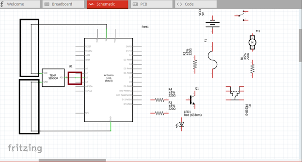
Select the electronic components needed for the circuit in the fritzing library. We need 1 arduino uno, 1 temperature sensor, 4 resistors, 1 led, 1 DC motor, 1 transistor, 1 switch, 1 fuse, 1 battery and 1 capacitor.

Arrange the components before constructing the circuit.
In arranging the components, place all the components for the input side (left side) of the arduino and the components for the output side (right side).
In this tutorial the input components will be the temperature sensor. The rest of the components are for the output side.

Now let us construct our circuit diagram. So at input side of our microcontroller is the temperature sensor. The sensor has three terminals, Vcc, Vout & ground terminal. The Vcc terminal will be connected to the 5V source output of the arduino, the Vout terminal will be our input signal. I will use pin A2 as our input pin. Then the ground terminal will be directed to the ground.
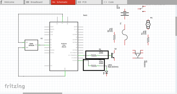
At the output side of our circuit is the led diode and the base resistor of the transistor. We will use two output pin, pin 11 & 13, though you can use any of them.
Then we have an external circuit connection between our electric fan, relay, fuse, switch, battery and a resistor. This separate circuit will be connected in series.
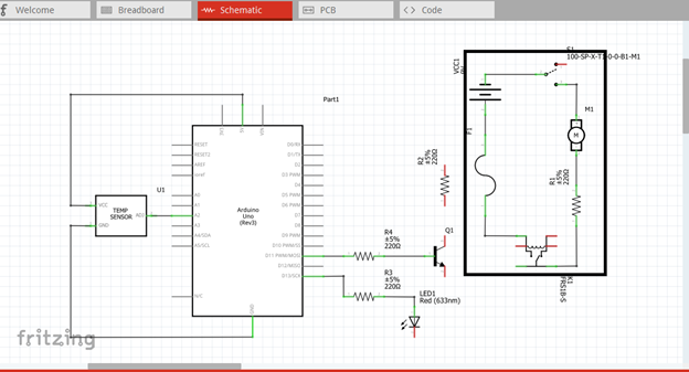
Now we need the output of our amplifier circuit to trigger the relay of the external circuit. So we connect the collector terminal to the input of the relay.

So here is our final circuit diagram.

When the temperature sensor detects that the temperature of the area is greater than the minimum room temperature, it will give an output signal. This output signal is then connected to the input pin 2 of the microcontroller.

The arduino uno is programmed to give output when the temperature is above the minimum temperature. The output signal will flow through the led diode and the base resistor of the transistor.

This amplified signal from the collector terminal is being fed to the input of the relay. When relay triggers, it will allow current to flow the circuit due to the source battery.

Now the current will flow through the external circuit and the fan will start turning on.

Part II. Code
Now let us do programming of our Arduino uno.
Click on code to start.

The input of our microcontroller is the output of our temperature sensor. We declare the input and output pins for our microcontroller. Pin 2 is the input pin and pin 11 & 13 as output pin.
int tempPin = 2;
int ledPin = 13;
int resPin = 11;

Since our main goal is to start the electric fan when temperature increase, so here we will assign an initial value for minimum and maximum temperature to start and stop the fan.
int temp;
int tempMin = 25; //Turn off the fan
int tempMax = 50; //Turn on the fan at 100 % speed
int fanSpeed;

For output and input setup.
void setup () {
pinMode(resPin, OUTPUT);
pinMode(ledPin, OUTPUT);
pinMode(tempPin, INPUT);
}

void loop () {
temp = readTemp();      //read the temperature
if (temp < tempMin) {   // if temp is lower than minimum temperature fan is off
    fanSpeed = 0;
    digitalWrite (resPin, LOW);
}

If ((temp >= tempMin) && (temp <= tempMax)) { // if temp is higher than minimum temperature
    fanspeed = map (temp, tempMin, tempMax);
    analogWrite (resPin, fanSpeed); // switch on the fan
}
If (temp > tempMax) {  //if temp is higher than tempMax turn on the led
DigitalWrite(ledPin, HIGH);
} else {                        // else turn off the led
digitalWrite(ledPin, LOW);
}

int readTemp() { //get the temperature and convert it to degree celsius
temp = analogRead(tempPin);
Return temp *0.4882;
}
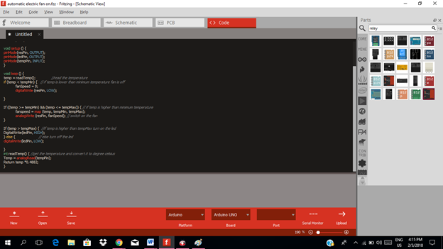
So here is our arduino codes.
int tempPin = 2;
int ledPin = 13;
int resPin = 11;
int temp;
int tempMin = 25;
int tempMax = 50;
int fanSpeed;
void setup () {
pinMode(resPin, OUTPUT);
pinMode(ledPin, OUTPUT);
pinMode(tempPin, INPUT);
}
void loop () {
temp = readTemp();
if (temp < tempMin) {
            fanSpeed = 0;
            digitalWrite (resPin, LOW);
}
If ((temp >= tempMin) && (temp <= tempMax)) { temperature
            fanspeed = map (temp, tempMin, tempMax);
            analogWrite (resPin, fanSpeed);
}
If (temp > tempMax) {
DigitalWrite(ledPin, HIGH);
} else {
digitalWrite(ledPin, LOW);
}
int readTemp() {
temp = analogRead(tempPin);
return temp *0.4882;
}
Part III. Breadboard
Click on the breadboard.

Arrange each component in the breadboard before connecting.

Now connect each component if you don’t know how to connect using breadboard just read my previous tutorial about how to construct a circuit in the breadboard

Application
The readers can create their own automatic fan controlled by the thermometer sensor and arduino uno.
Like the example below.
Curriculum
Here are my other tutorials for electronic projects.
ELECTRONIC PROJECTS
Posted on Utopian.io - Rewarding Open Source Contributors
nice sir:)
upvoted
thanks @janesmy081316
Thank you for the contribution. It has been approved.
You can contact us on Discord.
[utopian-moderator]
Hey @rfece143 I am @utopian-io. I have just upvoted you!
Achievements
Suggestions
Get Noticed!
Community-Driven Witness!
I am the first and only Steem Community-Driven Witness. Participate on Discord. Lets GROW TOGETHER!
Up-vote this comment to grow my power and help Open Source contributions like this one. Want to chat? Join me on Discord https://discord.gg/Pc8HG9x
greetings excellent information are very good tutorials that you present in your account!