Circuit Construction & Simulation |How to construct a basic circuit & simulating the output using the SimulIDE circuit simulator
What Will I Learn?
At the end of this tutorial:
The user will be able to construct & connect a circuit diagram and know how to measure & display the circuit output through simulation.
Requirements
Software
♦ SimulIDE application
Difficulty
♦ Basic
Tutorial Contents
Using the SimulIDE software, we will create a basic circuit diagram; know how to connect the circuit & displaying the output through simulation.
Part I. Circuit components
Before constructing a circuit, place all the necessary components needed in the circuit,
Open the SimulIDE application.

For this tutorial, we will construct the basic forward bias diode connection.
So in placing electronic components, just click on it and then drag to the circuit area.
I will place the diode in the circuit area.

Same process with the other components

To zoom in or zoom out the circuit, just scroll down to zoom in & scroll up to zoom out.

Part II. Circuit Connection
Before connecting the circuit, we can arrange each component
Right click on the component, and then you can rotate to your desired component position

Click the tip of the component pin, then a wire will display. Connect the wire to the tip of the other component’s pin.

In the figure below, the 5V source is being connected to the diode terminal.

Do the same to the other components, until the circuit diagram is completely connected.

Part III. Circuit Simulation
For circuit simulation we need a measuring device to measure the output voltage of the circuit.
We will use the voltmeter to measure the output of the circuit at the load resistor.
Click and drag the voltmeter to the circuit area.
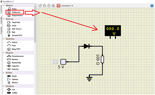
Connect the voltmeter across the resistor.

Turn on the circuit by clicking on the power circuit.

Switch on the 5V source by clicking the small box.

When the source is on, it will display a box with color orange, that’s the time the voltmeter display the output voltage, which is the expected output.
So if we measure the current, we will use the amperimeter and then connect it in series to the resistor.
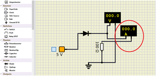

It display an output current of 42.7mA, which is the expected current to flow through the circuit.
So that’s all, follow this steps in constructing and simulating your circuits.
Curriculum
Here are my other tutorials for electronic projects.
**ELECTRONIC PROJECTS **
Tutorial 1
Tutorial 2
Tutorial 3
Tutorial 4
Tutorial 5
Tutorial 6
Posted on Utopian.io - Rewarding Open Source Contributors
Thank you for the contribution. It has been approved.
You can contact us on Discord.
[utopian-moderator]
Hey @sakibarifin, I just gave you a tip for your hard work on moderation. Upvote this comment to support the utopian moderators and increase your future rewards!
Hey @rfece143 I am @utopian-io. I have just upvoted you!
Achievements
Suggestions
Get Noticed!
Community-Driven Witness!
I am the first and only Steem Community-Driven Witness. Participate on Discord. Lets GROW TOGETHER!
Up-vote this comment to grow my power and help Open Source contributions like this one. Want to chat? Join me on Discord https://discord.gg/Pc8HG9x