Active buzzer with LDR and LED- Arduino
I just Wanted To Build A LDR Buzzer And Got Many Instructables Which Were Using To Do This Project.

This arduino basic tutorial for beginner. We will learn use piezzo buzzer, ldr and led in Arduino board.
PARTS NEEDED IN THIS TUTORIAL

CIRCUIT DIAGRAM

Just Follow The picture and the instruction i will give below icant upload fritzing diagram bcoz my pc cant install the app. Do The Wiring As Described In The Image
You Will Get Your LDR Buzzer Circuit Ready In A Couple Of Minutes!

Place the Buzzer, LDR and the LED to the vertical rail of the breadboard

PU the 220 ohms resistor to the possitve leg of the LED the long leg should be the possitve, and the short leg will bw the GND negative..

Wired the negtive GND of the parts, connect the short leg of the buzzer, the short leg of the LED, the left leg of the LDR, connect all that in one rail then connect it to the GND on the uno board.
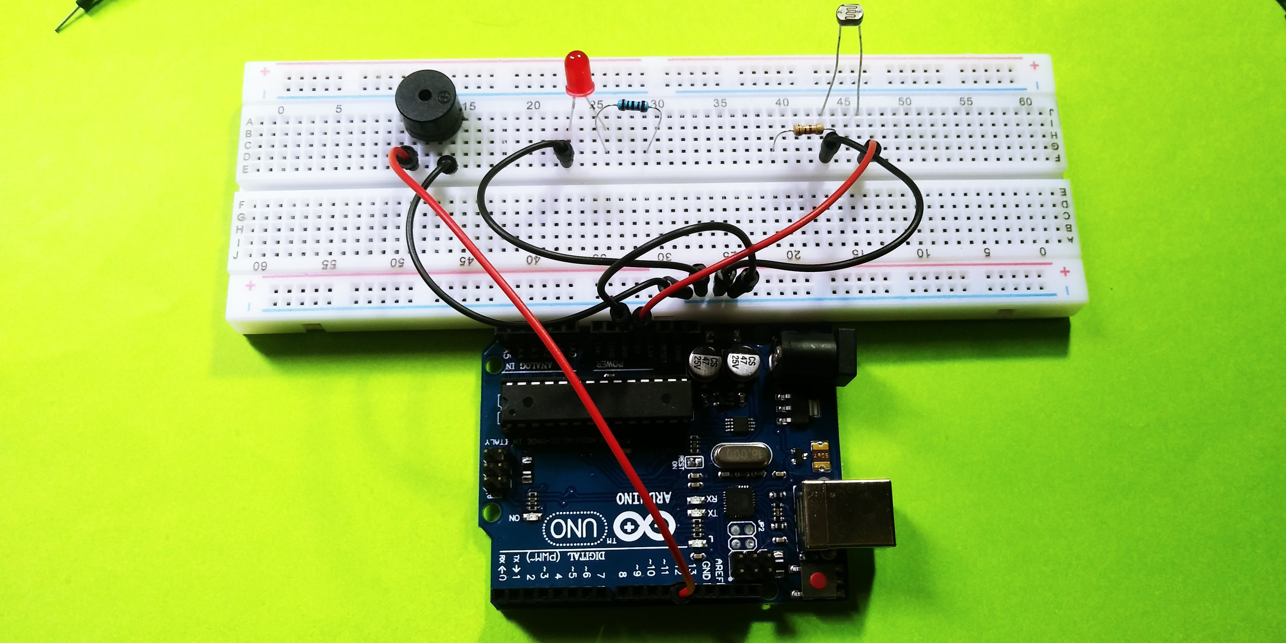
The right leg of the LDR to the 5v on the board, the long leg of the buzzer to the Digital pin 13.

The last Connect the left leg of the 10k ohms resistor of the LDR to the pin Analog (A0) on the board.
SOFTWARE
Before we work on our sketch, make sure to download the Arduino IDE for your specific operating system. I’ll leave a link to where you can download this software: https://www.arduino.cc/en/Main/Software

Arduino Sketch code for Buzzer, LDR and LED, the led pin should be in pin 13, the buzzer in pin 12 and the lrdpin in analog pin 0

CODE:
//set pin numbersconst int ledPin = 13;const int buzzerPin = 12;const int ldrPin = A0;void setup () { Serial.begin(9600); pinMode(ledPin, OUTPUT); pinMode(buzzerPin, OUTPUT); pinMode(ldrPin, INPUT);}void loop() { int ldrStatus = analogRead(ldrPin); //read the state of the LDR value
if (ldrStatus >= 400) {
tone(buzzerPin, 100); digitalWrite(ledPin, HIGH); delay(100);
noTone(buzzerPin); digitalWrite(ledPin, LOW); delay(100);
Serial.println("----------- ALARM ACTIVATED -----------"); } else {
noTone(buzzerPin); digitalWrite(ledPin, LOW);
Serial.println("ALARM DEACTIVATED"); }}Compile and Upload The Code And BOOM! There You Go!
You Just Made Your LDR Buzzer Without Any Hassles

when connecting an LDR to Arduino board, one would automatically go for one of the Analog pins, which gives us an ON/OFF state instead of a value. when the light is ON the BUzzer start the tone and the LED start blinking, if we block the light passing thru the ldr the buzzer and LED should be deactivated as you can ob the GIF image below..

I was inspired by this blog so thats it for my little project today, ig you like this please upvote and follow me @pakganern

Posted on Utopian.io - Rewarding Open Source Contributors
Thank you for the contribution. It has been approved.
You can contact us on Discord.
[utopian-moderator]
Hah! Can't wait to restart playing with my own Particle Photon, Chip and Arduino. You made my day :)
Your contribution cannot be approved yet. See the Utopian Rules. Please edit your contribution to reapply for approval.
You may edit your post here, as shown below:
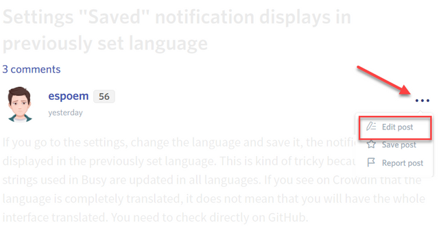
You can contact us on Discord.
[utopian-moderator]
already done sir!
Hey @pakganern I am @utopian-io. I have just upvoted you!
Achievements
Suggestions
Get Noticed!
Community-Driven Witness!
I am the first and only Steem Community-Driven Witness. Participate on Discord. Lets GROW TOGETHER!
Up-vote this comment to grow my power and help Open Source contributions like this one. Want to chat? Join me on Discord https://discord.gg/Pc8HG9x