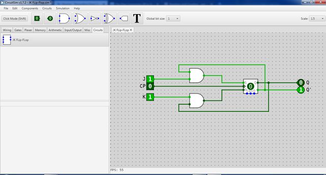
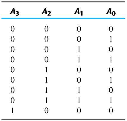
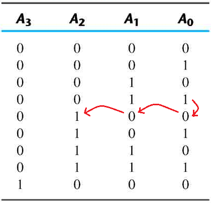
As we have discussed earlier in this tutorial, the ripple counter operates in a way that the lowest-order flip-flop is complemented by a clock pulse. A change in the state from 1 to 0 in the preceding flip-flop triggers the succeeding flip-flop, and complements it. For this tutorial, we will construct a 4-bit binary ripple counter using CircuitSim. Since we will be constructing a 4 bit ripple counter, there would be a four set of JK flip-flops by which the primaryJK flip-flop is connected with a clock pulse. However, the CircuitSim do not have a pre-configure circuit component for JK Flipflop. So, we need first to convert the SR flip-flop into a JK flip-flop using two sets of AND gates. This is done by connecting the input S and R to the output of the AND gate, while one input of the upper AND gate is connected to Q' output of the SR flip-flop.

At the same time the one input of the lower AND gate is connected to SR flip-flop's output terminal Q. After configuring the SR flip-flop to cater the functionality of the JK flip-flop, which include the set of input and output labeled as the terminals of a standard JK flip-flop. We change the name from new circuit to JK Flip-Flop. This is done by right clicking and selecting rename on the worksheet tab. After completing all describes steps, you should have come up up with what is shown on the figure below.
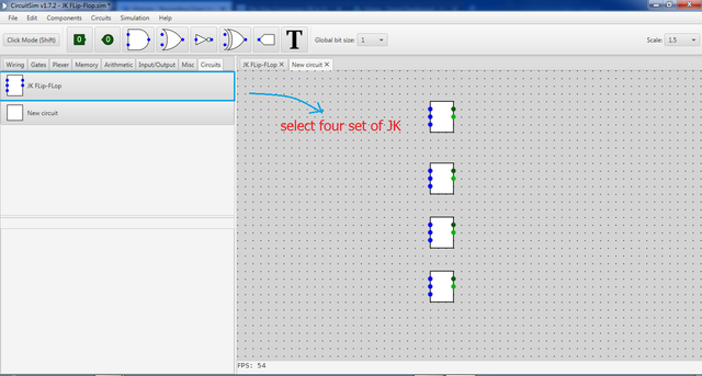
Now, we open a new circuit worksheet to construct the 4 bit binary ripple counter circuit which involves four set of JK flip-flop. Select from the component library under the circuit menu the JK flip-Flop component we have created a while ago. Put 4 set of this component by arranging it a vertical manner.
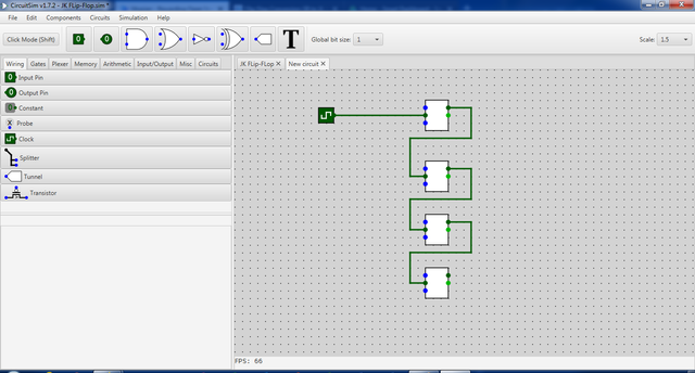
I said earlier that one lowest order JK flip-flop is to be connected to a clock pulse which used to trigger the next higher-state. To accomplish that, we connect a clock pulse on the upper JK Flip-Flop and connect the its output to the succeeding JK Flip-Flip. Do this for all JK Flip-Flops on the worksheet. In this way, we set the ripple action or logic by which the succeeding transition state is triggered by the preceding states.
 Then, we connect a unchangeable logic 1 on the J and K input of the JK Flip-Flop. This serves a constant logic base for the ripple counter. At the same time connect output component to Q terminal of the JK Flip-Flop. Label the output as A0, A1, A2, andA3, vertically. In addition, rename the circuit worksheet as Ripple Counter. Then, we connect a unchangeable logic 1 on the J and K input of the JK Flip-Flop. This serves a constant logic base for the ripple counter. At the same time connect output component to Q terminal of the JK Flip-Flop. Label the output as A0, A1, A2, andA3, vertically. In addition, rename the circuit worksheet as Ripple Counter.
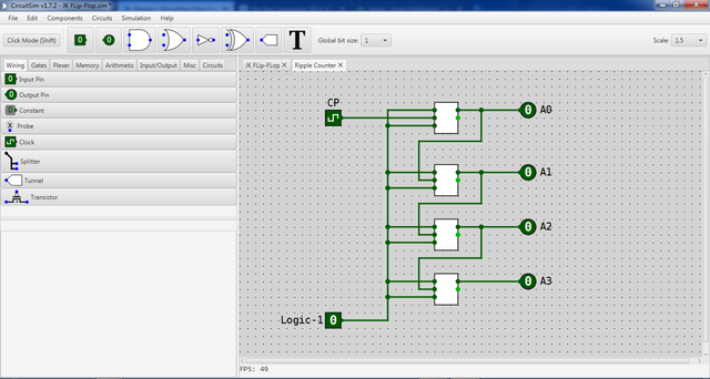
By connecting a logic-1 input for J and K of the JK Flop-Flop, we ensure that the operation of the circuit is dependent on the transition change primarily set by clock pulse with complementing the higher-order JK Flip-Flop by the preceded output of the immediate lower-order JK Flip-Flop in the circuit. |


Thank you for the contribution. It has been approved.
Personal Note:
This is a nicely styled tutorial. You have done a really good job. A little tip: you could give your design a bit more room to "breath" by inserting a
< br >above and below all of your images as well as above your headlines. That would give the text more white space.You can contact us on Discord.
[utopian-moderator]
Thank you @flauwy! Yes, I agree with you. I think i missed to have some ample breaks for the readers to breath. I would apply your tips in my next tutorial.
Great technology .....
Asynchronous counters are also called ripple-counters because of the way the clock pulse ripples it way through the flip-flops.
Boost Your Post. Send 0.100 STEEM or SBD and your post url on memo and we will resteem your post on 5000+ followers. check our account to see the follower count.
Hey @juecoree I am @utopian-io. I have just upvoted you!
Achievements
Community-Driven Witness!
I am the first and only Steem Community-Driven Witness. Participate on Discord. Lets GROW TOGETHER!
Up-vote this comment to grow my power and help Open Source contributions like this one. Want to chat? Join me on Discord https://discord.gg/Pc8HG9x
Great tutorial, but i feel you could have given a small definition on the binary ripple counter so that users will at least know what a binary ripple counter is.