Suggestion to Change the Schematic Symbol of Digital Components

QUCS can be downloaded at: https://sourceforge.net/projects/qucs/
Components
QUCS circuit simulator has an ability to work with analog and digital components. That is why I am using it not only for its free to use, but, also this software can integrate analog with digital components. Of course, many simulation software offers more and perform better than QUCS. For the fact that it is free to download and use, we can not under estimate this software.
There is a thing or section in digital component that bothers me. Some digital components have wrong schematic symbols. For some people they find it okay because it is just a symbol and it do not alter that function of the component. But for me, as a professional in the field of electronics I know the value of schematic symbols. It gives identity from component which is unique and no other components have the same symbol with others.
For me, schematic symbols are language use in electronics. With the schematic diagram using symbols, users can understand the function of the circuit and what components need to be used.
These schematic symbols must follow the international standards so that users all over the world can understand and to avoid confusions. So, suggested to enhance or change the schematic symbols for some digital components.
Proposal
The digital components which I believe have wrong schematic symbols are logic gates. They are the inverter, buffer, and gates, or gate, and more. The Integrated circuit (IC) symbols are ok because IC can be varied in symbols as long as they have rectangular in shape and with pins.
What I am proposing here is to change schematic symbols of logic gates in QUCS digital components.
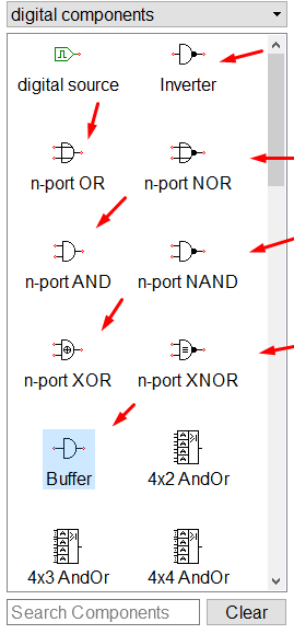
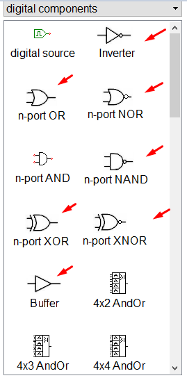
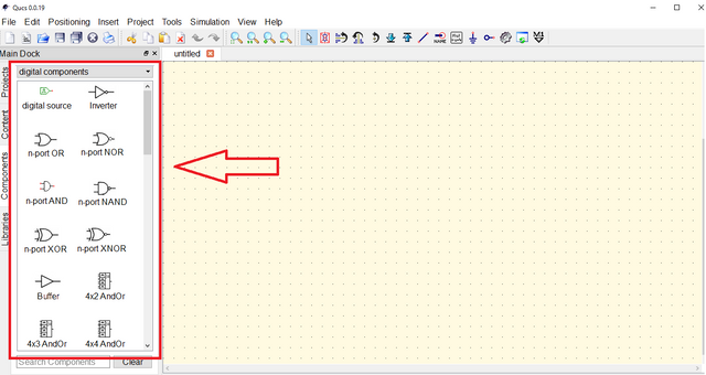
These are the current symbols used for logic gates in QUCS.
Here are the ANSI and IEC standard symbols for logic gates. ANSI stands for American National Standards Institute and IEC stands for International Electrotechnical Commission these are agencies assign to standardized symbols.
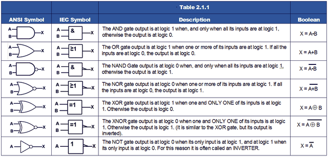
image source
From the symbols given by ANSI and IEC, some symbols used in QUCS are not there. These are inverter, OR gate, NOR gate, NAND gate, XOR gate, XNOR gate, and buffer. Therefore, these symbols must be change to follow the international standards for symbols.
Mockups / Examples
Here are the examples on how to implement this suggestion.
The current symbols stated will be changed.
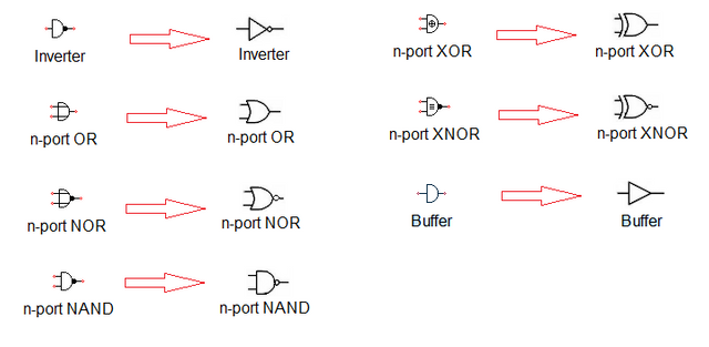
Digital component library will have a new look like this.
Benefits
Here are the benefits if implemented:
- QUCS logic gates will now follow the international standards for the schematic symbols.
- Users will not be confuse with the schematic symbols because it is the same to some software and reference books.
- Users all over the world can communicate well using the standard symbols.
Posted on Utopian.io - Rewarding Open Source Contributors
Thank you for the contribution. It has been approved.
You can contact us on Discord.
[utopian-moderator]
thank you @hsynterkr
Hey @thinkingmind I am @utopian-io. I have just upvoted you!
Achievements
Suggestions
Get Noticed!
Community-Driven Witness!
I am the first and only Steem Community-Driven Witness. Participate on Discord. Lets GROW TOGETHER!
Up-vote this comment to grow my power and help Open Source contributions like this one. Want to chat? Join me on Discord https://discord.gg/Pc8HG9x
Congratulations! This post has been upvoted by the communal account, @steemph.cebu by thinkingmind being run at Teenvestors Cebu (Road to Financial Freedom Channel). This service is exclusive to Steemians following the Steemph.cebu trail at Steemauto. Thank you for following Steemph.cebu curation trail!
Don't forget to join Steem PH Discord Server, our Discord Server for Philippines.