Arduino 101: Using a Hall effect sensor
What Will I Learn?
- You will learn the hall effect principle and know what the hall effect sensor is.
- You will learn how to use a hall effect sensor and integrate it with the arduino uno board.
- You will learn how to program the arduino board to make use of the hall effect sensor.
Requirements
Hardware
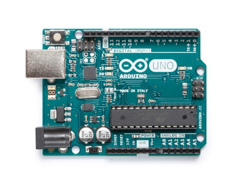
- Arduino Uno
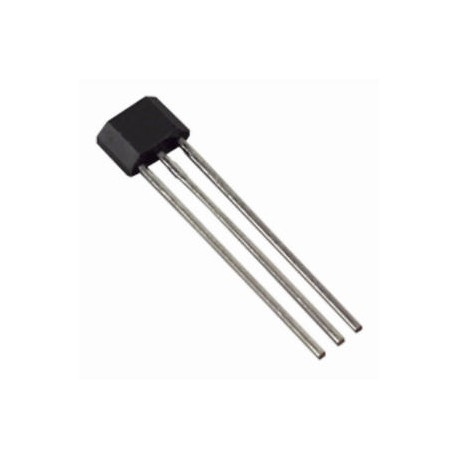
- Hall effect sensor
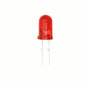
- LED
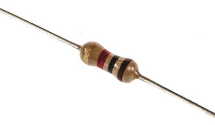
- Resistor (220 ohms & 10 kilo ohms)

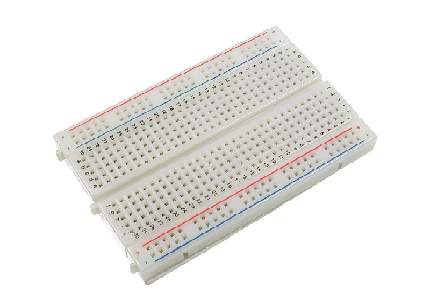
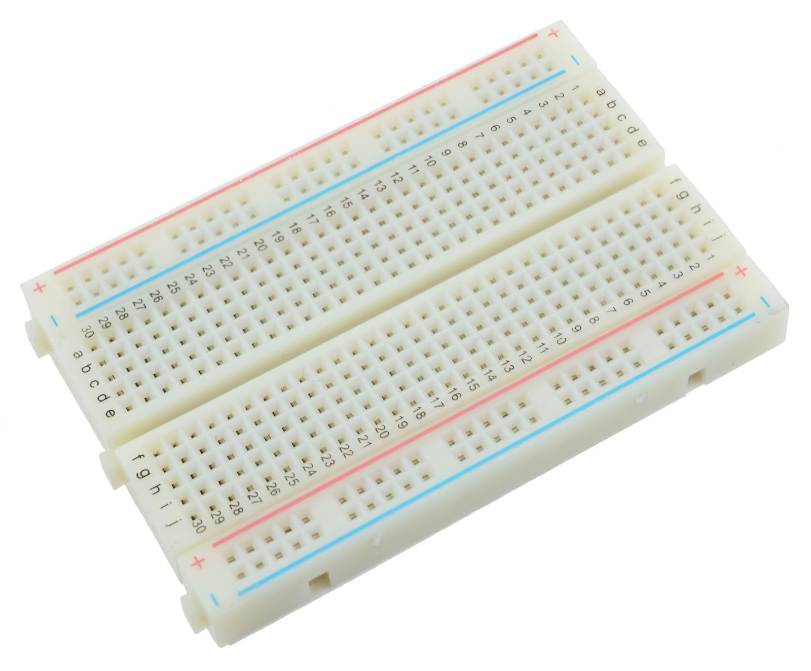
- Breadboard
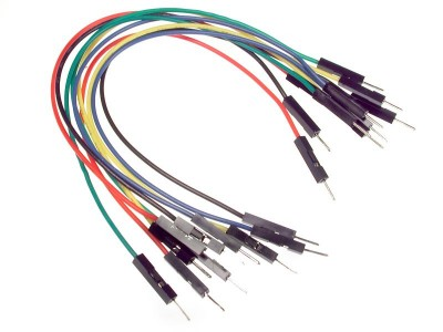
- Jumper Wires
- Computer

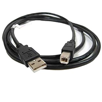
- USB type A to B cable
Software
- Arduino software/Arduino IDE
Knowledge
- Basic electronics and programming knowledge
Difficulty
- Basic
Project description
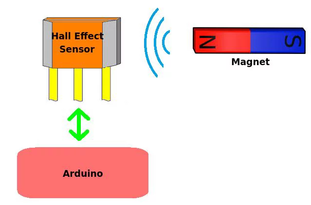
- This project uses a hall effect sensor, that uses the hall effect principle. This sensor is connected to the arduino uno board to serve as the input device and the LED as the output device. When a magnet is near the sensor, it will send a HIGH signal indicating that there is a magnetic field. Then the arduino uno board will process that signal and turn the LED on to indicate the sensors status. If the magnet is moved away from the sensor, it will give a LOW signal thus turning the LED off.
Component description
Arduino Uno - another type of arduino board that is used commonly by specialist and hobbyist because of its robust design. It is equipped with a microcontroller board that is based on ATMega328P with 14 advanced I/O pins (6 are PWM outputs), 6 analog inputs, 16 Mhz quartz crystal, a power jack, a USB port, an ICSP header and a reset button.Reference
Hall effect sensor - This is a special sensor that works on the hall effect principle. The principle states that, when a conductor/semiconductor with current flowing in one direction is placed perpendicular to a magnetic field, there would be a generated voltage at right angles to the current path. This change in voltage can be used by the arduino to detect if there is a magnet or not.Reference.
There are two main types of hall effect sensor: The latching and the non-latching hall effect sensor. The latching hall effect sensor(44E) gives out a HIGH output whenever the north pole of the magnet is placed nearby and it will not stop sending HIGH output even if the magnet is remove, only the south pole of the magnet can stop it from giving an output of HIGH. The other type of the sensor is the non-latching hall effect sensor (US5881 or US1881), where it sends a HIGH output whenever the north pole of the magnet is placed close to it and after removing the magnet, it will automatically send a LOW output without the need for the south pole of the magnet. Reference
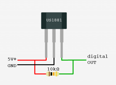
This are the pin outs of the hall effect sensor: VCC, GND, D0(digital output). It is hooked with a 10 kilo ohm resistor to pull the output of the hall sensor to 5 volts.
Tutorial Contents
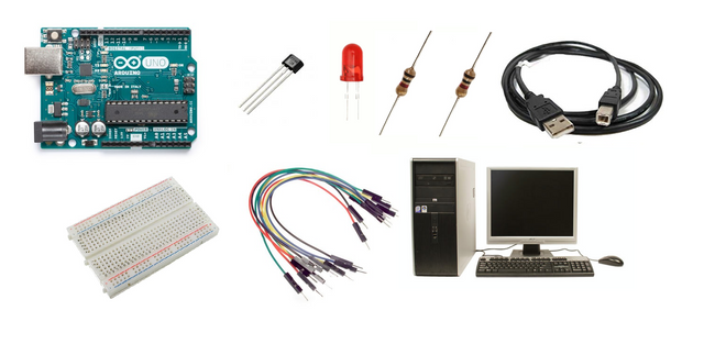
Step 1: Gather the parts
- You can purchase the components in your nearby electronics shop or order them up online.
Step 2: Construct the circuit
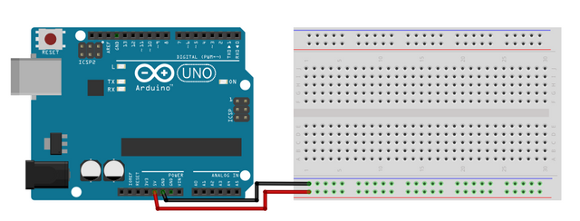
Connect the source
- Connect the 5 Volts pin of the arduino uno board into the top/bottom slot of the breadboard. The connections here are horizontally connected making it an ideal for the sources.
- Connect the GND pin of the arduino uno board into the top/bottom slot of the breadboard but make sure not to place them together to avoid shorting the arduino board.
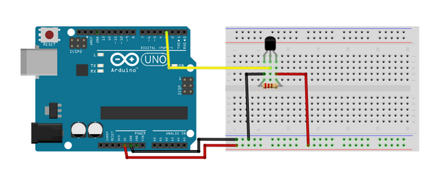
Connect the sensor
-Connect the 10 kilo ohms resistor to the ground and vcc pin of the hall effect sensor. This is to pull the output of the hall sensor to 5 volts.
- Connect the VCC/5V pin of the sensor to the voltage source in the breadboard.
- Connect the GND pin of the sensor to the common ground in the breadboard.
- Connect the D0 pin of the sensor to pin number 3 of the arduino uno board.
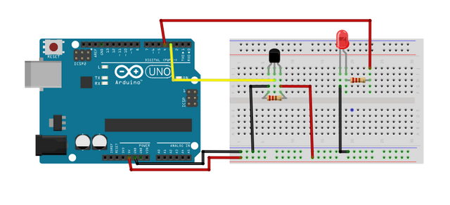
Connect the LED
-Connect the Anode(+) of the LED to a 220 ohm resistor that is connected to pin 4 of the arduino uno board. This resistor will protect the LED from over supply of current.
-Connect the Cathode(-) of the LED to the common ground.
Step 3: Programming
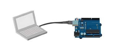
- Connect the arduino uno board to the computer by using the usb type a to b cable.
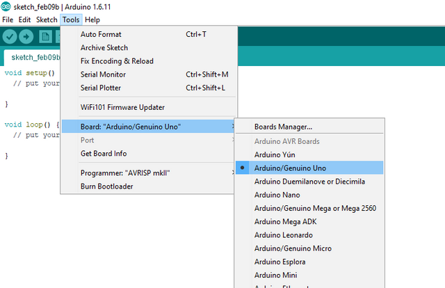
- Once the connection has established, open the arduino IDE and go to Tools > Board: > then select Arduino/Genuino Uno.
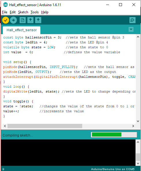
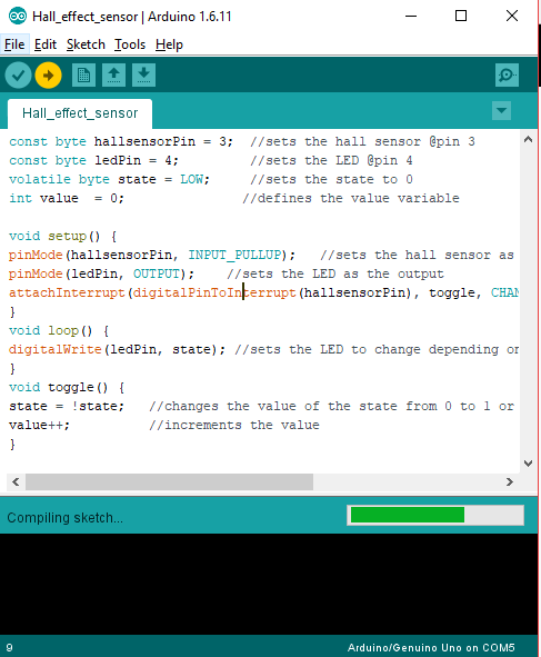
- Now, copy the paste below and paste it to your sketch in the arduino IDE.
const byte hallsensorPin = 3;  //sets the hall sensor @pin 3
const byte ledPin = 4;         //sets the LED @pin 4
volatile byte state = LOW;     //sets the state to 0
int value  = 0;               //defines the value variable
void setup() {
pinMode(hallsensorPin, INPUT_PULLUP);   //sets the hall sensor as the input
pinMode(ledPin, OUTPUT);    //sets the LED as the output
attachInterrupt(digitalPinToInterrupt(hallsensorPin), toggle, CHANGE); //Initialize the interrupt pin @pin 3
}
void loop() {
digitalWrite(ledPin, state); //sets the LED to change depending on the value of the state variable
}
void toggle() {
state = !state;   //changes the value of the state from 0 to 1 or 1-0
value++;          //increments the value
}
What this code does is it first sets the pins of the sensor and the LED, then it defines the 'state' and 'value' variables to be LOW at the start. In the setup command, it sets the hall sensor to be the input and the LED to be the output. In the
attachInterrupt(digitalPinToInterrupt(hallsensorPin), toggle, CHANGE);, it uses the interrupt pin of the arduino uno board (pins 2 & 3). When the hallsensorpin is interrupted by the magnetic field, it will trigger the toggle functionvoid toggle()which will then change the output from 0 - 1 or from 1 - 0. In the loop command, the LED is set to change whenever the 'state' changes its value from HIGH to LOW.
- After typing the code into your sketch, click the Verify button to save the sketch and compile the program. This will check for any errors in the code.
- If no errors were found, click the Upload button to start programming the arduino uno board.
Step 4: Testing
- After the programming is done, remove the board from the computer and connect it with a battery pack.
- Once booted up, get a piece of magnet and place it near the the sensor. If the LED lights up, that should be the north pole of the magnet.
- Now, remove the magnet away from the sensor. The LED should turn off to indicate that there is no more magnetic field in the area.
- Now flip the magnet, that side should be the south pole of the magnet. Now, place it near the sensor, the LED should not light up because it only works if it faces the north pole of the magnet, based on the hall effect principle.
Curriculum
Check out my other arduino tutorials below:
- Arduino 101: Using a KY-036 metal touch sensor
- Arduino 101: Using a Flame sensor module
- Arduino 101: Using a Capacitive Touch sensor to control an LED
- Arduino 101: Using a Reed switch
Posted on Utopian.io - Rewarding Open Source Contributors
Thank you for the contribution. It has been approved.
You can contact us on Discord.
[utopian-moderator]
Thank you very much sir! 😊
Hey @ted7 I am @utopian-io. I have just upvoted you!
Achievements
Suggestions
Get Noticed!
Community-Driven Witness!
I am the first and only Steem Community-Driven Witness. Participate on Discord. Lets GROW TOGETHER!
Up-vote this comment to grow my power and help Open Source contributions like this one. Want to chat? Join me on Discord https://discord.gg/Pc8HG9x
https://www.hlplanet.com/fixing-stick-drift-on-steam-deck/