Electronic Project 39: Alarm System Using the principle of LASER with the aid of LDR and arduino uno
What Will I Learn?
At the end of this tutorial:
♦ The readers will be able to create an alternative device that can be used for protection and aims to provide efficient home and industrial security system
♦ The readers will be able to know how the circuit works base from it theory of operation.
♦ Learn to apply the circuit in creating advance technology in the future electronic projects
Introduction
Today, security is the most important factor anywhere in the world. Technology develops day by day in the world. In this modern time we are facing different kinds of problem, and one of the major problems that we are facing is our home’s security. Nowadays, criminal will no longer choose when to attack.
That is why this tutorial was made for us to create an automatic security alarm system by which laser was used. This system is designed to detect intruders who break into our house.
You can read more about laser here

Requirements
Electronic Components
♦ Arduino Uno
♦ Laser
♦ Piezo buzzer
♦ LED
♦ Light dependent resistor
♦ Resistor
♦ Breadboard
♦ Connecting wires
Software
♦ Fritzing application
Difficulty
♦ Advance
Tutorial Contents
Using the fritzing software, we will create our circuit diagram, arduino codes and prototype using the breadboard
Part I. Schematic Diagram
So first let us construct our circuit diagram.
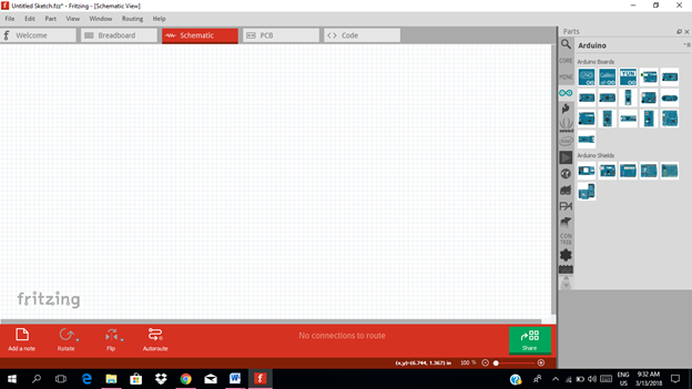
Select the electronic components needed for the circuit in the fritzing library. We need 1 arduino uno, 1 light sensor (LDR), 4 resistors, 1 laser, 1 piezo buzzer , 1 transistor and 1 LED.
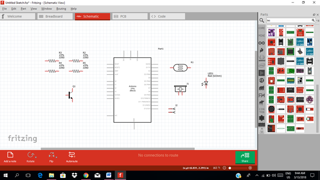
Arrange the components before constructing the circuit.
In arranging the components, place all the components for the input side (left side) of the arduino and the components for the output side (right side).
At the input side of our circuit we have the laser, our source of light and the light sensor that will detect the light coming from the laser. While at the output side of our circuit, we have the amplifier circuit and the alarm circuit composed of buzzer for sound alarm and the led for the light signal.
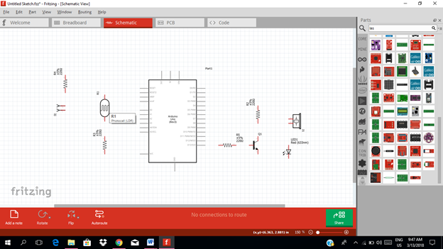
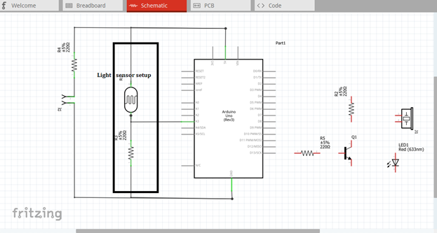
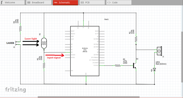
Now let us construct our circuit diagram. We need to connect a voltage source to the laser, so we will use the 5V output of the arduino and connect it to the laser as shown below. The laser, unfortunately, is not available right now at the this software, so I use the female header pins where the laser shoud be connected.
Then our light sensor must be constructed next to the laser so that the light will be directly detected. The light sensor will be connected to the source voltage and to the input pin of our microcontroller. So here, I use the pin A3 as our input pin. You can use any of the following analog input pin of the arduino uno.
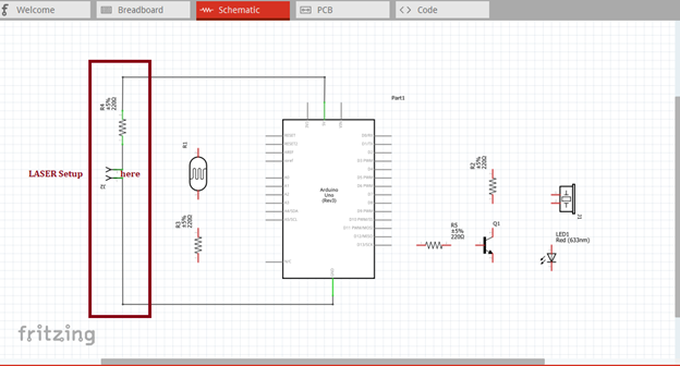
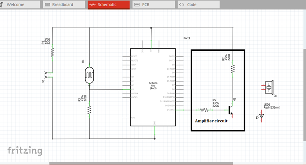
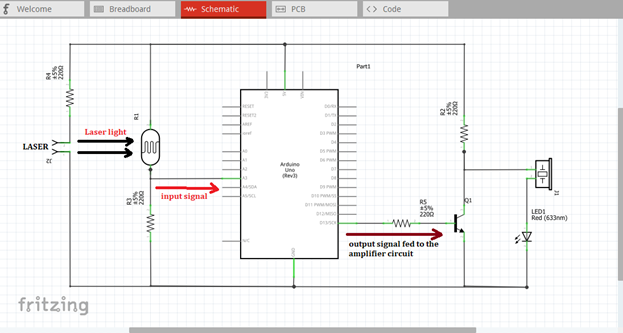
The output signal from pin 13 is connected to the base resistor of our amplifier circuit. This signal will be amplified so that it can drive the external circuit as shown in the figure.
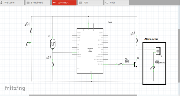
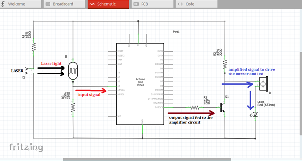
The alarm setup is constructed using a buzzer and led connected in series. In order to drive this circuit we need to connect this to the output of our amplifier circuit. The amplified output will trigger this alarm circuit when the laser and light sensor communication is being cut or interfered.
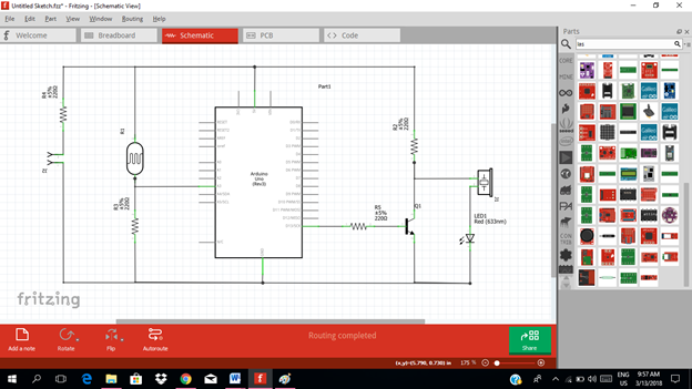
Now this is our final circuit diagram.
Theory of operation:
The basic operation in this circuit is that the laser transmitter emits the laser beam and on the opposite side where there is a light sensor that receives or detects the laser beam. If that laser beam is interrupted or the light sensor doesn’t receive the light, the resistance of the light dependent resistor increases which decreases the voltage inside the circuit. Then the output becomes low then the corresponding tripper gets triggered which automatically alarms the buzzer and the also the LED that plays as an indicator in the alarm system.
This alarm system will be placed in the area where you want security such that in case of home invasions the alarm will be triggered.
The laser and light sensor must be place opposite with each other so that the light from the laser is directly absorbed by the light sensor. Once this connection is interfered, a signal will flow through the input pin 3 of the microcontroller making it to trigger.
The microcontroller will give output signal at pin 13 that is connected to the amplifier circuit. Then this signal will be amplified as it flows through the amplifier circuit.
The amplified signal will now trigger the alarm circuit.
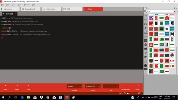
Part II. Code
Now let us do programming of our Arduino uno.
Click on code to start.

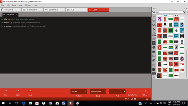
The input pin for our microcontroller from the output of the light sensor is the analog pin 3 and the output pin is pin 13.
int ldrPin = 1;  //light dependent resistor input pin
int resPin = 13; //output pin for our power amplifier circuit
int sensorValue = 0; //initial value store in the light sensor terminal
void setup() {
pinMode (ldrPin, INPUT);        //light sensor output terminal as input value
pinMode(resPin, OUTPUT);   //for the resistor pin signal to the amplifier circuit
}
void loop(){
sensorValue = analogRead(ldrPin); //read analog value from the light sensor output
if(sensorValue<=1000){
digitalWrite(resPin, HIGH); //give output at pin 13 to be amplified at the amplifier circuit
else
digitalWrite(resPin, LOW); //no output at pin 13
}

Here are our arduino codes.
int ldrPin = 1;  //light dependent resistor input pin
int resPin = 13; //output pin for our power amplifier circuit
int sensorValue = 0; //initial value store in the light sensor terminal
  void setup() {
pinMode (ldrPin, INPUT);        //light sensor output terminal as input value
pinMode(resPin, OUTPUT);   //for the resistor pin signal to the amplifier circuit
}
void loop(){
sensorValue = analogRead(ldrPin); //read analog value from the light sensor output
if(sensorValue<=1000){
digitalWrite(resPin, HIGH); //give output at pin 13 to be amplified at the amplifier circuit
else
digitalWrite(resPin, LOW); //no output at pin 13
}
Part III. Breadboard
Click on the breadboard.
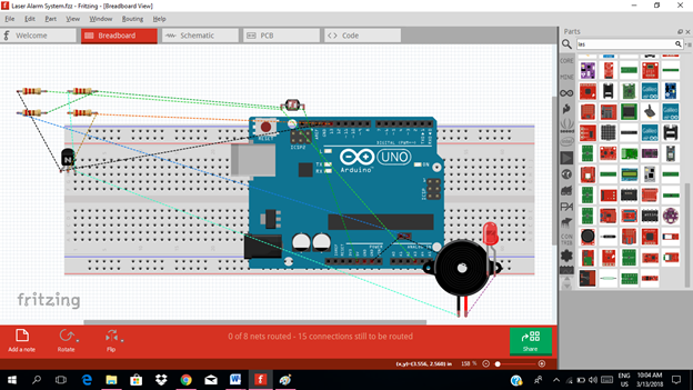
Arrange each component in the breadboard before connecting.
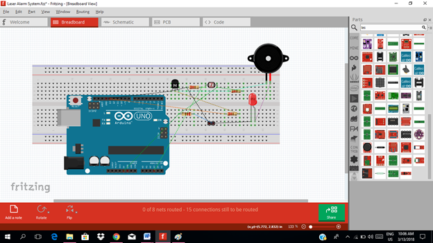
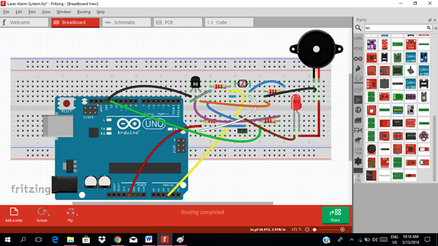
Now connect each component if you don’t know how to connect using breadboard just read my previous tutorial about how to construct a circuit in the breadboard
Application
The readers can create their own security alarm system. This device is mainly designed for security purposes. It is useful for home security and establishment’s security.
Curriculum
Here are my other tutorials for electronic projects.
ELECTRONIC PROJECTS
Posted on Utopian.io - Rewarding Open Source Contributors
Thank you for the contribution. It has been approved.
You can contact us on Discord.
[utopian-moderator]
Hey @cha0s0000, I just gave you a tip for your hard work on moderation. Upvote this comment to support the utopian moderators and increase your future rewards!
Hi rfece143 ,
I found an article with similar content here:
BoldspiritTravels on a budget: Visiting “el Museo d’oro” ("the Gold Museum”) in Bogota, Colombia [Solo backpacking on a budget in Latin America]
This is because you likely copy and pasted some form of content --
whether it be your own or not. This is not an accusation of wrongdoing,
but merely an informative comment for the reader.
If you get repeated warnings we will start to flag all rfece143 posts!
Hey @rfece143 I am @utopian-io. I have just upvoted you!
Achievements
Community-Driven Witness!
I am the first and only Steem Community-Driven Witness. Participate on Discord. Lets GROW TOGETHER!
Up-vote this comment to grow my power and help Open Source contributions like this one. Want to chat? Join me on Discord https://discord.gg/Pc8HG9x