Solar Power System with Up-cycled Components Part 1
Solar Power System with Up-cycled Components.
Scope of Project.
The objective of this project is to assemble and install a stand-alone solar power system (Photo Voltaic or PV) . My goal is to run 2 LED light bulbs in fixtures on my workbench and charge/maintain my power tool batteries. My estimated load will be 2 x 10W/LED bulbs, and 85W for the charger while it is actively charging batteries. As I have included my cordless power tools into my emergency preparedness plan, the ability to charge those batteries off the grid is a necessity. For our usage when the power fails out here in the winter.
Personal history
I became interested in solar power after I saw my first Space Shuttle launch. I want to say it was 1980 something and I was just a tiny tinker gnome. The ability for a satellite to obtain its power from sunlight was absolutely fascinating to a young tinkerer who had a habit of taking his toys apart to make new toys. Heck some of those creations even worked, if you used enough imagination anyway.
Around 2001, A friend turned me on to Home Power Magazine. I loved that rag and for the longest time, I was a subscriber. Each month was showcased on yet another build and my lust for solar power continued to grow. Unfortunately, about this time just the panels alone were running in the $6/Watt range. I pushed it off in my mind and
waited for the economies of scale for prices to drop to my budget. FYI I was the second tick for Guerrilla Conservation on their old map. I stole the incandescent bulbs from the fixtures in the apartment building I lived in and replaced them all with CFL bulbs. In the letter I left in the manager's box I stated what I had done and why along with
explaining the savings they would experience. The entire time I lived there those bulbs remained so I guess I was successful he didn't give a rip.
What finally tipped me over the edge was that I was able to obtain 3 deep cycle batteries due to routine maintenance on the large UPS in our data center. I collected quite the box of 10-12 gauge wire and Anderson connectors, Fuses, and other bits from smaller UPS's that had failed. I was just waiting for the moment that I could start implementing a small PV setup.
I had planned on going with the 45W Harbor Freight Kit, it can be found for as low as $130 with the right combo of coupons and sales. However from friends that have gone that route, the charge controller just did not hold up to 24x7 usage and died in the first year. So I kept looking and waited until the price was right to buy standard components without a proprietary kit.
Initial Design and how it changed.
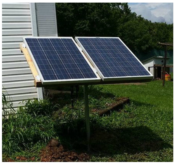
I had initially only planned on installing the Renogy 100W starter kit on a pallet wood ground mount and calling it done. But then after placing the order, I realized that I had a bunch of credit from trading in college books and DVD's that I forgot about having. The result was that I doubled the system generation capacity with a second 100W panel and the other bits and pieces to wire them in parallel. I had also originally planned on building a ground sled mount out of Pallet at a fixed angle but wound up fabricating a pole mount reusing a satellite dish bracket and pole. The old dish was a bit of an eyesore just standing there looking dumb with coax hanging off of it. I was going to pull it anyway (along with the other dish when I noticed that it was graduated for angles of elevation. Whoo hoo that's it! I will get as much of the pipe out of the ground as possible and build a mount using the graduated bracket. And if it does not work I'll go back to the sled idea.
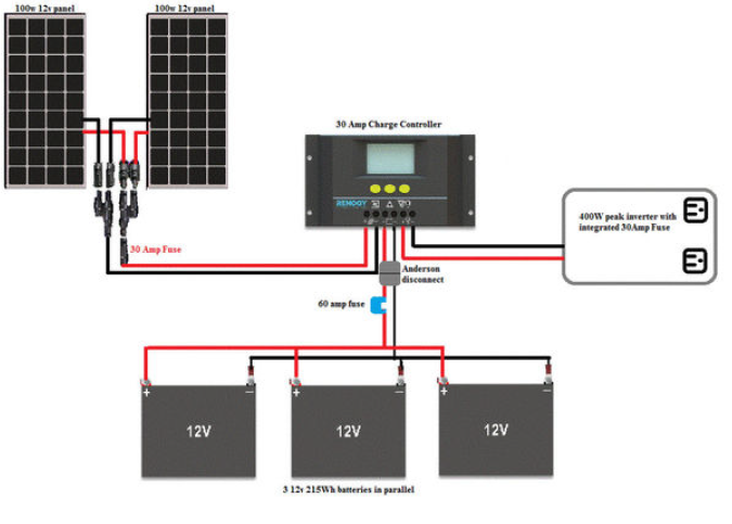
This was my basic wiring diagram on how I did it.
All documentation for the Renogy Products listed can be found here.
https://www.renogy.com/
I am not being sponsored by Renogy and honestly, their customer support is lacking after my controller died.
Anyway enough speculation and planning on to the good part.
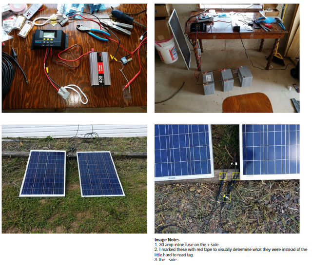
Step 1: Inventory of parts and tools used.
Stuff Bought From Amazon
I had about $160, in store credit and trade on my account so my total out of pocket was about $200. I started off by ordering the following 100W kit. https://www.amazon.com/dp/B01N5L2GM9?ref_=ams_ad_dp_ttl&th=1 209.99 mine is the older model with a slightly different controller and you will see that prices have even decreased from when I purchased mine. And now they even have a kit with all the stuff bought below in one box.
100-Watt polycrystalline solar panel.
One pair of 20 feet MC4 cables
One set of Z Brackets
Renogy PWM 30A LCD Display charge controller
Then I added another 100w panel http://amzn.com/B00CAVMMMG 135.99
A Y connector so that I could connect the 2 panels in series. http://amzn.com/B00BCWRB48 12.99
A 30 Amp inline fuse for the PV positive http://amzn.com/B00J954BTI $18.00
A pair of MC4 assembly/disassembly tools http://amzn.com/B00BCWZFN2 $6.99
The second set of Z Brackets http://amzn.com/B00BR3KFKE $13.49
Stuff bought from the local farm and home store.
2 x 2 gauge cable ring terminals $3
4 x 2 - 8 Gauge clamping ring terminal $4
6 x 6mm x 20mm standard thread bolts $2
60lb bag of ready-mix concrete $2.97
Stuff scrounged from scrap piles and saved from the landfill over the years.
400W - 12VDC to 110VAC inverter (work was going to toss this so I saved it)
4 gauge electrical cable (left over from new electrical service installation)
10 gauge wire in various lengths (salvaged from various UPS)
2 Anderson quick connects (UPS salvage and already on wire)
3 x 215 Wh Deep Cycle Batteries (salvaged from a UPS)
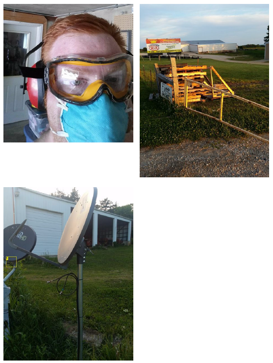
Wildblue Satellite dish pole and bracket (removed from the yard)
Pallet Wood (from local trailer manufacturer)
Treated 2x4 (storm salvage)
###Stuff from stock on hand
Red and Black Electrical Tape
10 Gauge ring terminals
10 Gauge butt connectors
2 3/4" Deck screws
1 1/2" Deck Screws
1" drywall screws
Rosin Core Solder
Tools Used
Reciprocating saw with metal cutting blade
Circular saw
Impact driver
Hammer drill with 1/2 Masonry Bit
Socket Set
pocket knife
6 in 1 screwdriver
Wire Cutters
Wire Crimper
Tape Measure
Protractor
Bubble level
Lensatic Compass (direction finding and aiming)
Shovel (for digging holes)
Hoe (concrete mixing and packing)
Storage Tub (concrete mixing)
F250 (borrowed to pick up pallets, thanks John & Jared)
Safety Equipment
Goggles
Hearing Protection
N95 Dust mask
Wool Blanket (to cover the panels)
Step 2: Battery Bank Building.
While I was waiting for the main components to arrive I figured I could get my battery bank ready to go.
I needed to make some jumper cables between each battery. Then I used 2 Anderson quick disconnects and some bits of wire to make the battery to controller connections. I also wanted to add a fuse so if I had an oops moment it would blow before my batteries did.
The batteries are being wired in parallel. Each positive will be connected to each other positive using jumper wires. The same goes for the negative leg. The difference between parallel and series. Parallel increases capacity, while series increases voltage. Had I connected them in series I would have a 36V battery bank and would
probably have some toasted electronics.
This is what I came up with
I reccommend getting some booster cables for your large gauge wire. The stuff I have is aluminum and building code says no no. However I dont think there is much harm with the terminals being tinned.
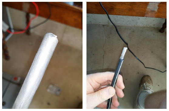
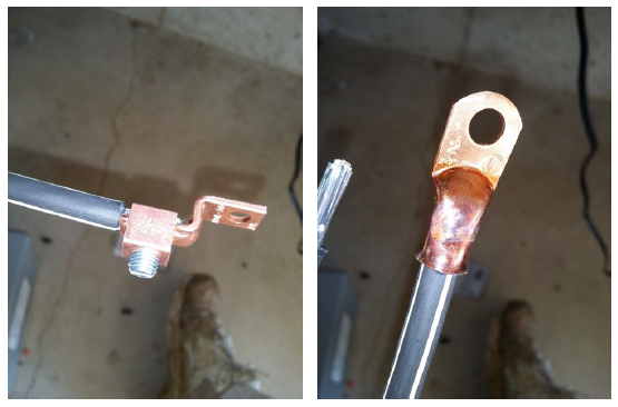
- I measured and cut 4 x 1ft sections of 4 gauge wire. The wire was left over from an electrical service installation.
- Using a pocket knife I scored the insulation about 3/4 of an inch from the tip, then used my wire cutters to strip the insulation.
- 2 of the bus bars used the screw clamp terminal end, however, the hardware store only had 6 so I had to use 2 solder/crimp ring terminals
- Open the screw terminal, insert the wire, then tighten it back down using a pair of plyers to hold the terminal for the final turns.
- To solder the 2 ring terminals on, I first clamped them into my metal vise.
- Then I used a small butane torch to heat the copper terminal and filled the well with molten solder.
- While applying heat to the terminal end I preheated the cable end in the flame and gently inserted it into the terminal taking care not to splash solder.
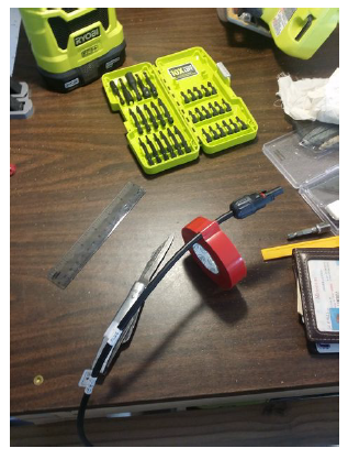
- After your jumpers are made color one double clamp and one clamp/lug terminal wire with red electrical tape to indicate +
Allow the terminal to cool before removing the connector from the vise.
Now that the large gage jumpers are made it is time to make the small gauge connection for the Charge controller.
This one is pretty simple. I selected the Anderson connector that had the longest pieces of wire. Then I selected another that was wired so that when the connection is made they would line up + red to +red and - black to - black.
As the wire already had blade connectors that fit the 60 Amp fuse that I had I just stuck it inline on the positive side. then used electrical tape to ensure that it did not inadvertently short out on the - side.
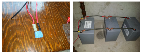
The black side was not as long as the red due to the addition of a fuse so I crimped on another length of wire using a 10 gauge butt connector. I Then finished the lead off by Crimping a 10 gauge ring terminal on the free ends.
The side that goes into the charge controller just has 1/4" insulation stripped off with a twist on the free end to keep it from fraying while being inserted.
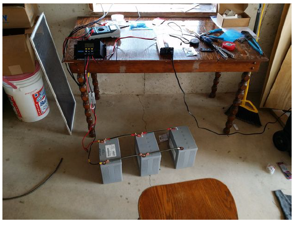
Step 3: Bench test.
Now that all the components are in, and the battery jumper cables are made it is time to test it all out to make sure everything works before building the mount.
Of note when connecting and disconnecting solar panels make sure you cover them so that they are not generating electricity to prevent shorts and turning your fancy green energy producers into slag.
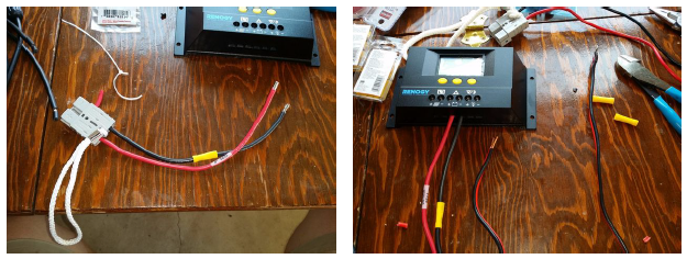
Starting with the Charge controller I made my connections right to left.
- Attach included temperature probe to the charge controller.
- Strip and connect the cables for the inverter to the load port on the charge controller ensuring correct polarity.
- Connect the controller side of the battery cable to the battery terminals ensuring correct polarity.
- Cover the solar panels and make note of which side is negative. Attach both negatives to their respective Y junction.
- Connect both positives to their respective Y junction.
- Connect the inline fuse to the single end of the positive junction
- Connect the negative lead to the negative junction then connect it to the charge controller
- Connect the positive lead to the fuse on the positive junction and connect it to the charge controller
- Ensure your batteries are wired up correctly and join the quick connect.
- Note at this point the charge controller is now energized and will display the status of the solar array and Load.
- Uncover the solar panels and enjoy collecting energy from the sun.
By pressing the menu cycle button I was able to verify that my panels were producing 7 Amps of power and my tool battery charger was using 3 Amps. I was also able to verify the voltages by touching the probes of my multimeter to the screw terminals on the charge controller. I noticed 13.21V on the solar array, 13.19 on the battery, and 13.18 on the load terminals.
Using the MC4 wrenches I disconnected the battery bank and disassembled the panels using the reverse of how I assembled above. The only difference is that I marked the positive side with red electrical tape before disconnecting it to make hook up easier after passing cable through the wall.
Ill have part 2 posted in a couple days. I figured with the amount of steps that are involved with this one It would be better to break it in two.
Thanks for reading this far.
Here is the second part
https://steemit.com/solar/@motinkergnome/solar-power-system-with-up-cycled-components-part-2
Congratulations! This post has been upvoted by SteemMakers. We are a community based project that aims to support makers and DIYers on the blockchain in every way possible. Find out more about us on our website: www.steemmakers.com.
If you like our work, please consider upvoting this comment to support the growth of our community. Thank you.
I really can't wait to see the concluding part of the Tutorial, This is a Nice Piece. I must commend.
Thanks ufxpression. I try to be overly detailed when I make stuff if anything so I can teach my kids later. I have a bunch more projects that are getting moved over to Steemit. I suggest checking out some of my older posts for more stuff I have built/tinkered with. To say I have ecletic taste is an understaitment.
By popular demand here is part 2
https://steemit.com/solar/@motinkergnome/solar-power-system-with-up-cycled-components-part-2
You have been scouted by @promo-mentors. We are a community of new and veteran Steemians and we are always on the look out for promising authors.
I would like to invite you to our discord group https://discord.gg/vDPAFqb.
When you are there send me a message if you get lost! (My Discord name is the same as here on Steemit)
ok I screwed something up, The link said expired. my discord is MoTinkerGnome# 5874
Sorry, my bad. Try this one and please let me know
https://discord.gg/SjXdM6K
Thank you Dedicatedguy. I appreciate it. That link got me right in. :)
Thats a fine, detailed article. Im looking forward to reading the next part.
Thank you, I am hoping to get it up this evening or tomorrow. I just need to get the formatting properly done.
Here ya go part 2
https://steemit.com/solar/@motinkergnome/solar-power-system-with-up-cycled-components-part-2
Great instructable! Your cable cuts are really clean kudos! By any chance might you have calculated the DoD(Depth of Discharge)? SteemOn!
I honestly never really got too deep into what it would support. I calculated the amp/hour capacity of the pack at about 50 A/H. But just sort of guestimated what my depth of discharge would have been. THe charge controller would cut output at like 10.5 volts to prevent over discharge from the factory so I just left it.
Nice work !
Thank you.