CALCULATION OF THE NUMBER OF PLATES OF A RECTIFICATION COLUMN. (Part -1)
CALCULATION OF THE NUMBER OF PLATES OF A RECTIFICATION COLUMN. (Part -1)
In this first part of the publication, it is not intended to make the total calculation of a distillation column, but an application of the enthalpy - composition diagrams. This calculation will be restricted only to binary solutions and will use the corresponding enthalpy-composition diagram. One of the most important data that must be calculated in a rectification column is the number of plates needed to achieve, from a given feed, the desired separation. The number of plates and the flow of the power supply will establish the mechanical details of the tower, such as height, diameter, etc.
The nomenclature to be used for the calculation is the following:
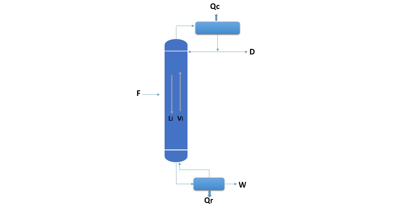
Figure 1.
Source: @rossanavictora
F: Mass flow rate to the column.
xF: composition of the feed with respect to the most volatile component, infractions by weight or molar fractions.
hF: enthalpy of the feed (with respect to a reference state).
D: Mass flow of the product obtained by the top of the column (stop).
xD: composition of D.
hD: Enthalpy of D.
W: Mass flow of the product obtained from the bottom of the column (bottom).
xW: composition of W.
hW: enthalpy of W.
Qc: heat extracted from the condenser.
Qr: heat delivered in the reboiler.
R: external reflux ratio.
Hi: steam enthalpy Vi.
hi: enthalpy of liquid Li.
General balance of the column:
The data needed to start the calculation of the tower are the following: feed data (F, xF, hF), composition of the top and bottom products (xD, xW). With these data you can start to make the balance of matter and component:
Balance sheet:
F = D + W (Equation 1)
Balance in the most volatile component:
F.xF = D.xD + W.xW (Equation 2)
Energy balance:
F.hF + QR = D.hD + W.hW + QC (Equation 3)
F.hF = D.hD + W.hW + (Qc - Qr) (Equation 4)
The values of Qc and Qr are defined as follows:
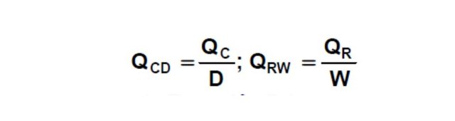
Replacing and rearranging in equation 4:
F.hF = D (hD + QCD) + W (hW - QRW) (Equation 5)
In Equation 5, the terms have been rearranged in a way as if all the heat Qr will be delivered to stream W and heat Qc will be extracted from stream D.
If the following three points are taken:
F (hF; xF)
D '(hD + QcD; xD)
W '(hW - QrW; xW)
And they are located, with these coordinates, in the enthalpy - composition diagram of the system they will be colinear, as shown in Figure 2 since it corresponds to a system where one current is divided into two others, as seen in figure 3.
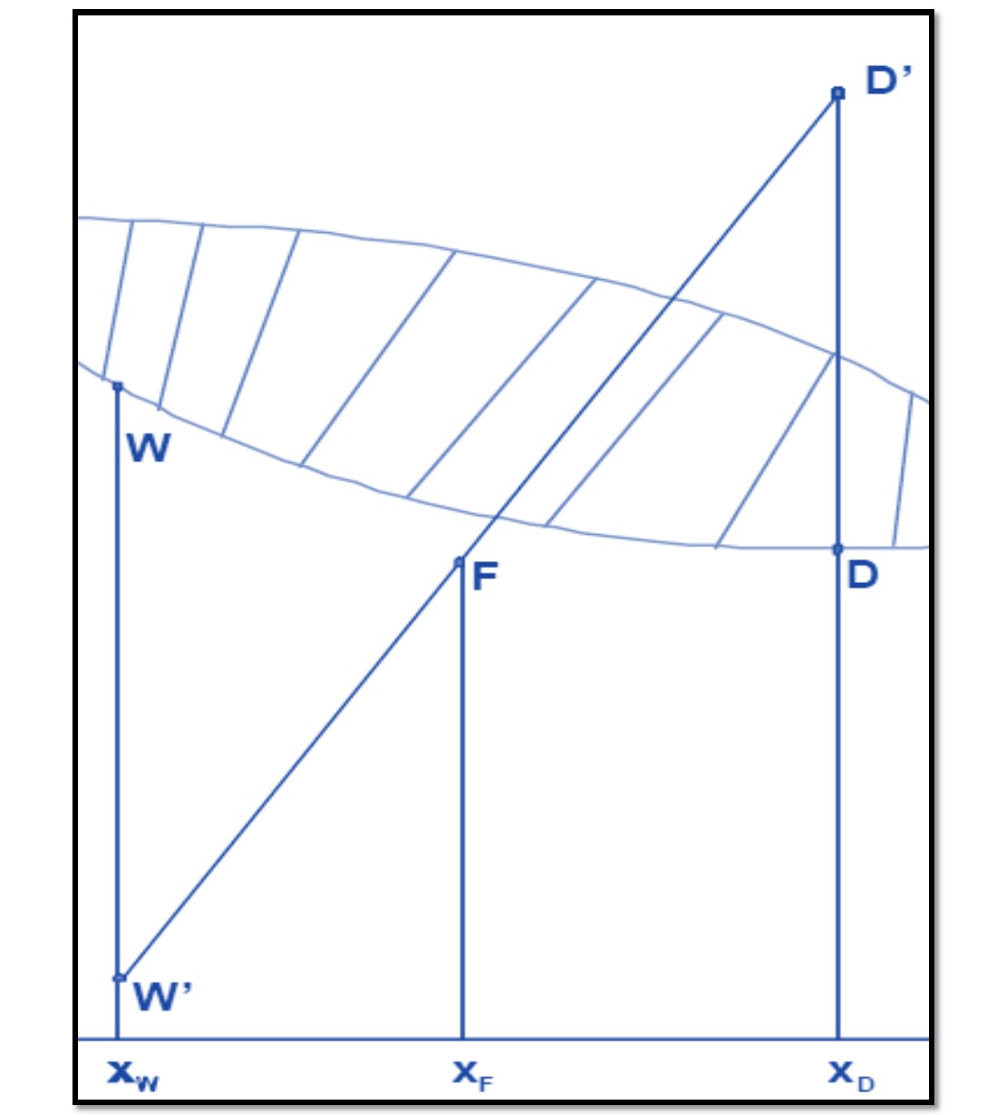
Figure 2
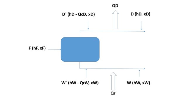
Figure 3
Source: @rossanavictora
The previous balance corresponds to the balance of mass, component, and energy of the entire column. To calculate the number of plates of the same, the balance is continued starting from the top of the same (starting with the condenser and then plate by plate)
Balance in the condenser:
In this item, the usual nomenclature of the bibliography will be followed: the plates are numbered from the top starting with 1, and the currents of both steam and liquid, have as subscript the plate number.
The composition of a liquid stream in its most volatile component (in fractions weight or molars) is designated as x, and those of a vapor stream, such as y. The steam current from the first plate of the column enters the condenser (according to the nomenclature used, it will be No. 1). Since this vapor stream comes from plate 1, it will be called V1. The mentioned stream is completely condensed (at its boiling temperature) and divided into two: one that is extracted from the column as a stop product (D) and the other returns to it as reflux (this current enters the upper part of plate 1, although there is no plate 0, it will be called L0, while in the condenser the heat QC will be extracted, which will be the one that condenses all the vapor V1, Figure 4 shows all the tributary and effluent currents of the condenser.
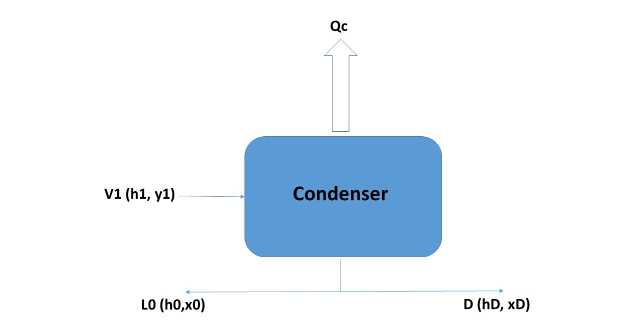
Figure 4
Source: @rossanavictora
The balances around the condenser will be:
V1 = L0 + D (Equation 6)
(mass balance)
V1.y1 = L0.x0 + D.xD (Equation 7)
(component balance)
As shown in Figure 4, the composition of the currents L0 and D are equal, so that Equation 7, can be placed as follows:
V1.y1 = (L0 + D) xD
The energy balance will be:
V1.H1 = L0.h0 + D.hD + QC (Equation 8)
Since the enthalpies of the currents L0 and D are equal, Equation 8 can be put as:
V1.H1 = (L0 + D) hD + QC --- > Qc = V1.H1 - (L0 + D) .hD (Equation 9)
Replacing in Equation 9, V1 by its equal of Equation 6:
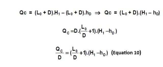
The L0 / D ratio is called the "external reflux ratio" and is the ratio between the mass flow rate that is returned to the column with respect to the mass flow that is extracted as the top product from the top of the column. The external reflux ratio is usually called the letter R.
As shown in Equation 10, if the external reflux ratio is set, the heat QC is fixed, so that, according to Equation 3, when QC is set, QR is determined. The external reflux ratio (R) is a data that must be provided for the calculation of the tower.
The system corresponding to the condenser could be synthesized as indicated by the Figure 5, where the current V1 enters and separates in the currents L0 and D. assumes that the quantity of heat QC is extracted from current D (so the quantity of heat per unit of mass to be extracted from D will be: QCD = QC / D).
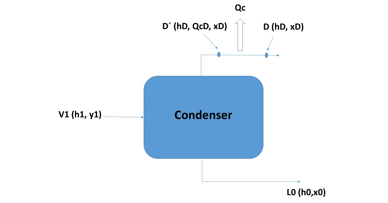
Figure 5
Source: @rossanavictora
According to Figure 5 the three collinear points in the enthalpy-composition diagram of the system are:
V1 (H1, y1)
L0 (h0, x0)
D '(hD + QcD, xD)
What will have to be determined is the position of the points in the diagram.
L0 and D (as seen in Figure 4) are two currents that have the same composition and enthalpy, in addition as it is assumed that the vapors of stream V1 are completely condensed without subcooling, L0 and D must be located on the curve of liquid (or bubble) being its concentration xD. The point of the current V1, like this, is a saturated vapor and that condenses totally in the condenser must be in the curve of vapor (or dew) being its concentration also xD. The point corresponding to D' has the concentration xD but its enthalpy is greater than that of D in QcD. Figure 6 shows the location of these points.
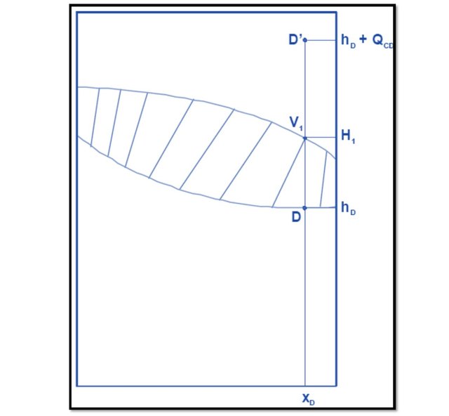
Figure 6.
Source: @rossanavictora
Balance on the first course:
As seen in Figure 7, the tributary currents to plate 1 are: V2 and L0 and the effluents are: V1 and L1.
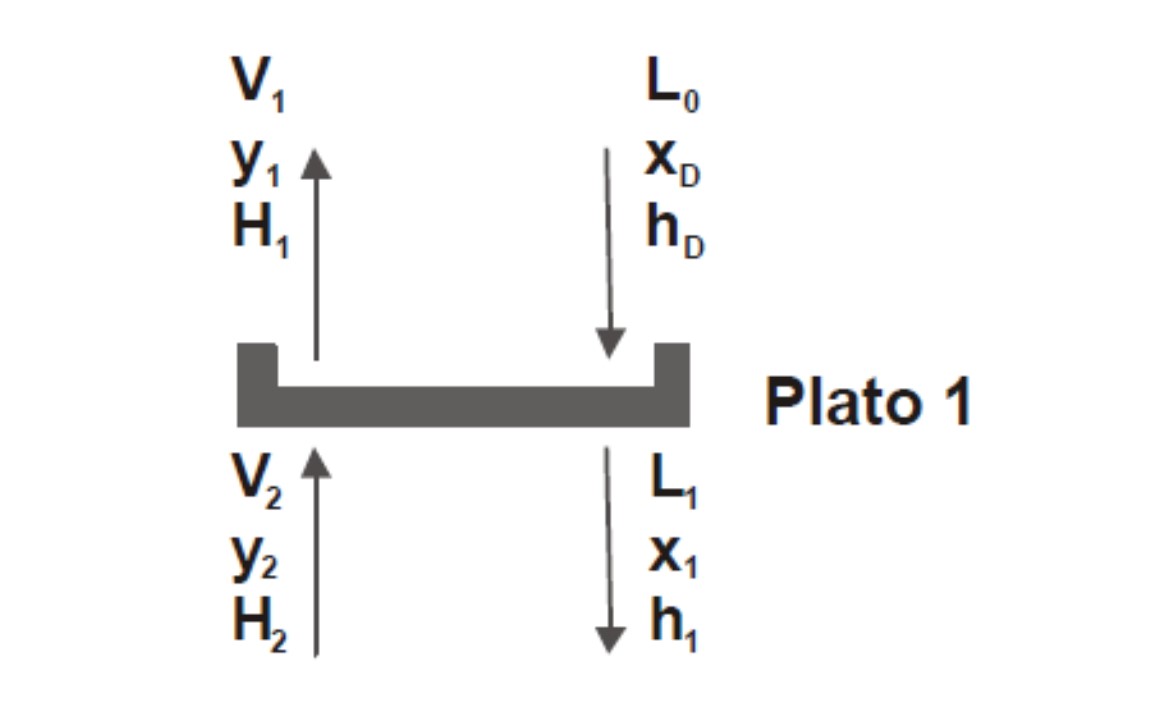
Figure 7
Source: @rossanavictora
Making the balances:
V2 + L0 = V1 + L1
(balance sheet)
Rearranging the terms of the equation:
V2 - L1 = V1 - L0
But as seen in Equation 6:
V1 - L0 = D
So that:
V2 - L1 = D Þ V2 = L1 + D (Equation 11)
V2.y2 + L0.xD = V1.y1 + L1.x1
(balance per component)
Rearranging the terms:
V2.y2 - L1.x1 = V1.y1 - L0.xD
According to Equation 7: V1.y1 - L0.x0 = D.xD, replacing in the previous one:
V2.y2 - L1.x1 = D.xD -----> V2.y2 = L 1.x1 + D.xD (Equation 12)
V2.H2 + L0.hD = V1.H1 + L1.h1
(energy balance)
Rearranging:
V2.H2 - L1.h1 = V1.H1 - L0.Hd
According to Equation 8: V1.H1 - L0.hD = D.hD + QC, replacing in the previous one:
V2.H2 - L1.h1 = D.hD + QC ----> V2.H2 - L1.h1 = D (hD + QCD) (Equation 13)
As it is observed, three equations are proposed: Equation 11, 12 and 13. The data that are known about these are:
V1: it is determined if the reflux ratio R.
y1: has the same composition as xD.
H1: is the enthalpy of the saturated vapor V1; as the composition of V1 is known, H1 also since it is saturated steam, therefore it is on the vapor or dew curve.
L0: is determined by the reflux ratio.
xD: composition of the distillate.
hD: enthalpy of current D, is on the bubble curve.
The unknown data of these three equations are V2; y2; H2; L1; x1; h1. As you can see, there are six unknowns and only three equations, so the system is not solvable. In order to be able to solve this system, the concept of *** theoretical plate *** is introduced:
It is said that a plate is theoretical when the vapor and liquid streams that leave the plate (in this case V1 and L1) are in equilibrium with each other.
Introducing this concept, in the plate 1, if the point V1 (H1, y1) is determined and in turn is in equilibrium with L1 (h1, x1) the two points will be connected by a line of equilibrium, being V1 on the curve of vapor and L1 on the liquid curve, as shown in Figure 8.
Raising the net balance in plate 1, according to Equations 11, 12 and 13 the three points that are collinear (as seen in Figure 9):
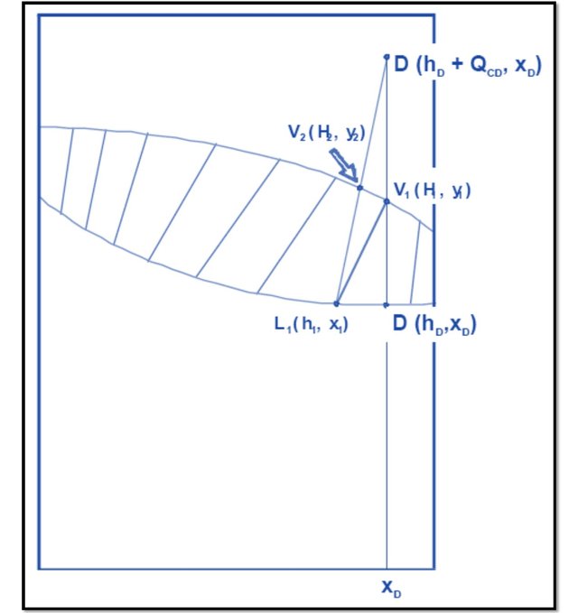
Figure 8
Source: @rossanavictora
L1 (h1, x1)
V2 (H2, x2)
D '(hD + QCD, xD)
In this way, the point corresponding to V2 (which remains on the vapor curve since it is a saturated vapor) is determined. In this way, by defining the theoretical plate, all the unknowns of plate 1 are solved.
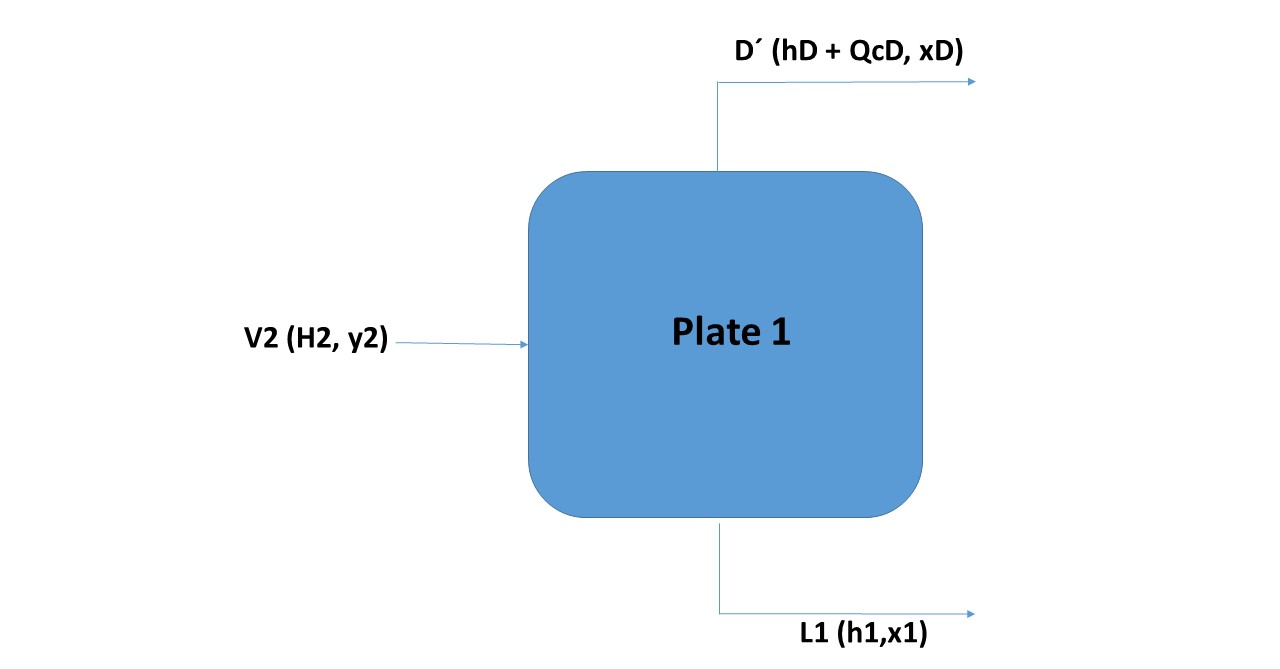
Figure 9.
Source: @rossanavictora
In Figure 8 is observed, the line joining the point corresponding to V1 with L1 is obviously a line of equilibrium. The line that connects point D 'with L1 (with which V2 is defined) is called the operation line.
Observing Figure 7, a balance line joins the points corresponding to the vapor and liquid streams that leave the plate (which by the definition of theoretical plate, must be in equilibrium), in the previous example V1 with L1; in turn, an operation line joins the points of the currents entering and leaving the same side of the plate (in the example: L1 with V2).
Then the mass and energy balances of all the dishes that follow the 1 should be made. In order to simplify the method, the calculation will be made on a generic plate i (which will be any between plate 1 and the feed plate).
Balance on a generic plate and above the feeding plate:
In Figure 10 is observed, plate i is any plate that is between plate 1 and the feed plate. The dotted line represents the limits of the system where the mass and energy balances will be made. The tributary streams to the system are Vi + 1 (this vapor current comes from the lower plate to the i, which evidently if the plates are numbered from the top down, will be the plate i + 1. The effluent streams of the system will be L1 and D In addition, the quantity of heat QC is extracted from the condenser.
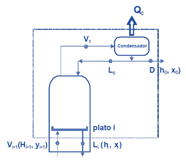
Figure 10
Source: @rossanavictora
Therefore the balance sheets will be the following:
Vi + 1 = Li + D
(mass balance)
Vi + 1.yi + 1 = Li.xi + D.xD
(component balance)
Vi + 1.Hi + 1 = L 1.hi + D.hD + Qc
Vi + 1.Hi + 1 = L1.hi + D (hD + QcD)
(energy balance)
As shown in Figure 11, the three collinear points are Vi + 1, Li and D '. This line that connects these three points is an operation line and connects the corresponding point to the vapor that reaches the bottom surface of the plate i with the point corresponding to the liquid that comes out through the lower surface of the plate.
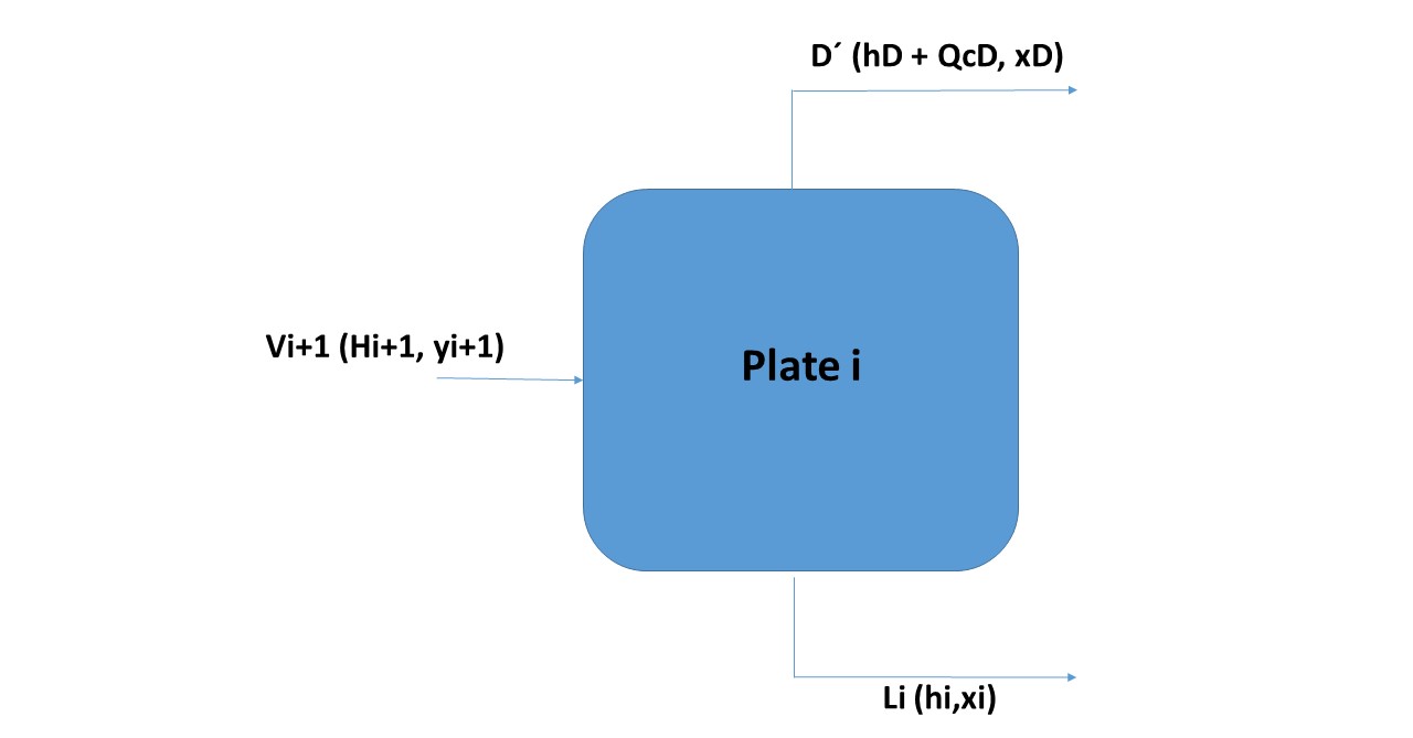
Figure 11
Source: @rossanavictora
I like it n good night my friend <3
Thank you :)