How to make a circuit board using the laser iron (LUT)?
source
Here's a writeup of a simple DIY project for making PCB (printed circuit board) at home.
LUT method is to transfer the toner to the PCB by heating it . For the manufacture of printed circuit boards in this way , we need a laser printer.
Many consider the LUT method (laser iron) to be purely a domestic invention. In fact, this is not so. In civilized countries, this process is called Iron Toner Transfer for PCB Making and for these keywords in Google there is a lot of interesting, especially if you look for video. I will confine myself to a few pictures from the smartphone. Some people advocate using glossy inkjet photo paper, but I think this is a waste and the cheap glossy laser paper comes off easier.
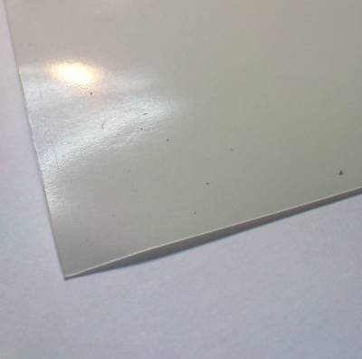
So, the most important thing is to find a decent laser printer (I use Canon LBP6000). The main criterion is that the toner does not save much when printing. The printout should be slightly felt with a finger on the surface of the paper and do not get very visible when looking at the lamp "at the lumen". The next component of the process is paper. Precisely the basis of the labels. In fact, besides paper for stickers, it is found in self-adhesive wallpaper and ORACAL advertising materials (I like this base most of all - it is dense and does not twist). Pruning ORACAL-a can be free or zanedorogo vymutit in any even a small advertising company engaged in outdoor advertising and signs. On the one hand, the base looks glossy.
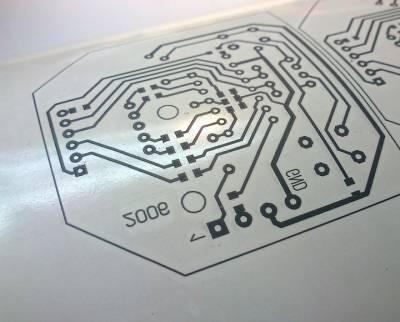
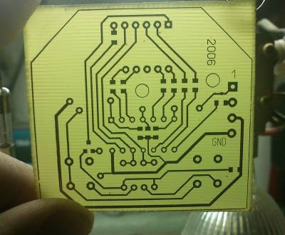
It is on the glossy side and you need to print the tracks of your future payment. Here there are 2 important nuances: the tracks must be printed in a mirror manner so that the letters on the surface of the board are unreadable. And the second - turn off the toner economy and choose black color for the tracks when printing. Fingerprints are not touched - even microscopic grease contamination will cause poor adhesion of the toner to the copper of the board.
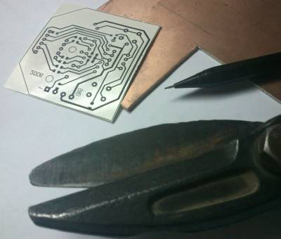
The floor of the case is done. Now cut off the brutal scissors over the iron piece of fiberglass a little more than the future board. The edges of the material are slightly jarring during heating and the toner does not adhere well to them. It is better to throw out the extra 5mm material than get a marriage on the board.
I cut off the cut piece with fine sandpaper. Without fanaticism - the foil is very thin. The stubborn surface sticks better to the toner.
Do not touch the sanded copper! Let me remind you: fat from fingers is the main enemy of the process!
Then we prepare the "press". For many years now I have been using the book by the well-known author of Skritek on circuitry of high-quality equipment. This book is quite thick and provides both good thermal insulation and even pressure of the board.
At the beginning, place the sheet of paper on the workpiece accurately. That at "ironing" this sandwich has not parted, the first "tack" should be done through one page. The temperature of the iron for LUT should be about 180-190 degrees Celsius. Usually this is about three points on the scale of the temperature controller.
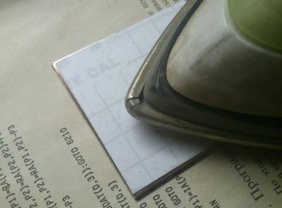
When the leaf is slightly adhered to the surface of the future board, turn the page and iron our LUT sandwich directly. Without strong pressure. Toner sticks not from pressure, but from temperature. So do not rush, iron smoothly, letting the board warm up. Tracks should, as it were, slightly protrude through the paper.
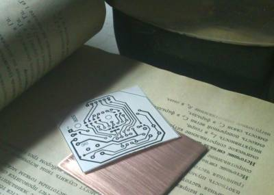
Next, remove the iron and let the board cool to a temperature of about 50-60 degrees. We hook the edge of the paper with a fingernail or any thin object and raise the base of the self-adhesive. There should be something like this:
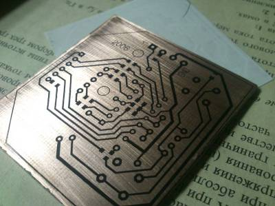
Now we are armed with a magnifying glass and carefully monitor the LUT-imprint obtained. Do not neglect optics. It allows you to save a lot of nerves during the debugging phase of the device. 8-) The existing cracks can be retouched with an indelible marker for CD-DVD discs.
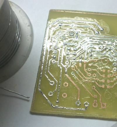
When the marker dries (about 10 minutes later), the board can be pasted onto the back of the narrow tape and dipped in a jar with a copper-etching solution. I use the old-fashioned - chlorine iron. If you are going to make the LUT method a double-sided board, then before dipping into the solution the second side with a continuous layer of copper should be sealed with a wide tape.
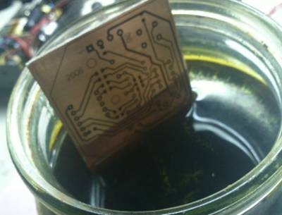
The process is faster if the solution is heated to 40-45 degrees Celsius. It is impossible to heat above - at a temperature of more than 50 degrees the solution quickly degrades. In the process of etching, periodically remove the board and monitor the result (so that our thin tracks do not eat the solution).
After finishing the etching, rinse the board under running water. CAUTION! If a drop of solution falls on the clothes, the clothes will be spoiled. Spots from ferric chloride are not washed off the fabric.
Now with a clean and etched board you need to remove the pattern from the toner. I use vatka, moistened with R-646 solvent (for nitro dyes). Toner is easily laundered.
Further I put on a board a flux and a puddle. Previously, used spirtoknifol. But then alcohol was banned i and I switched to rosin, dissolved in a solvent (the same P-646). The smell was not very appetizing, and when Lukey L2010 appeared on the market, I did not use it. Soldering iron, solder is similar to PIC-61 (I buy ASAHI 60/40).
After tinning the entire board, I remove the surplus solder with a copper sheath from the shielded wires. When the domestic stocks of braid were over, they began to buy Chinese. It is already saturated with rosin.
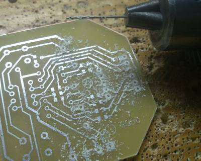
After removing the solder, I launder the charge again R-646. Then you can start drilling holes. If you make a double-sided board, then you do not need to drill holes at this stage of the LUT (only a couple on the edges of the board to match the pattern of the tracks).
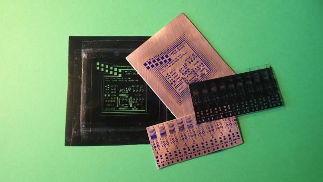
After drilling, the one-way board by the laser irons method is ready - it is possible to seal the detachments and washing after the soldering fee (who alcohol, and who and stinky P-646) can admire the result:
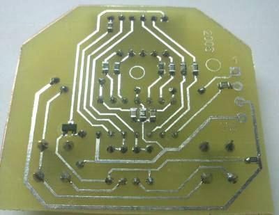
It was a display card of the device for overvoltage protection.
If you need to make a double-sided board, at the stage before tinning the board we drill a pair of reference holes (usually at the corners of the board), sand the copper like the first side, using a pair of needles in the drilled holes, we combine the pattern and iron. After "ironing" and removing the paper, glue the side with already etched paths and etch with a wide adhesive tape, as in the case of a one-way board. Further all the same - zaluzhivanie (two sides) and drilling.
Good luck! And do not be nervous - if you do everything in a hurry and calmly, the result will be immediately positive.
References:
Build Your Own Printed Circuit Board
by Al Williams
Making Printed Circuit Boards
by Jan Axelson
Support @steemstem and the #steemstem project - curating and supporting quality STEM related content on Steemit
Nice..
This worth trying
Thumb 👍 up
This post has received a 0.68 % upvote from thanks to: @punjolife.
For more information, click here!!!!
Send minimum 0.100 SBD to bid for votes.
Before sending a transfer to @minnowhelper, verify that your publication meets these conditions (http://www.minnowhelper.com/conditions.php). After the transfer is made, no claims will be received.
The Minnowhelper team is still looking for investors (Minimum 10 SP), if you are interested in this, read the conditions of how to invest click here!!!
ROI Calculator for Investors click here!!!
This post has received a 0.68 % upvote from @booster thanks to: @punjolife.
Really neat, I like seeing this DIY circuit board creation process! Thanks for putting this together.
Awesome! Very good tutorial - I never knew how exactly to make your own.
Thanks
Thanks for sharing. The result looks awesome pcb maker : PCB manufacturing process