How To Build A Christmas Light Chaser -Explained With Clear Images
Hello steemians! hope you had a lovely weekend? Mine was an interesting one, that's if one removes the stress in it and oh before I forget, compliments of the season to you all! Guess everyone has put up good decorations for the festive season.
In the spirit of Christmas, today am going to be doing a post on how to build your own Christmas led light chaser circuit. So let's get started.
The components we are going to be using for this circuit are;
- NE 555 IC
- CD4017
- Resistors
- LEDs
- Capacitors
- Bread board
- A voltage supply.
Don't be scared of the components, this is a do it yourself post, I will explain in detail what you need to know about the components. And secondly I have already calculated all the values so you don't need to worry about that. I did that so as not to scare people away from electronics. In other for us to achieve this we are going to be following these procedures; 1 To generate a clock from our 555 timer IC. 2 To connect our 4017 IC to our 555 timer IC. But before then let us start by knowing our components.
1. Bread board
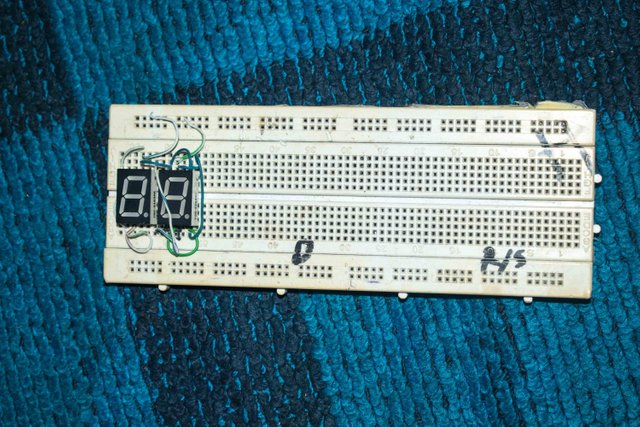
A bread board is a type of circuit board used for testing circuits and some times, for building temporary circuit in which one does not desire to solder.
2. Capacitor
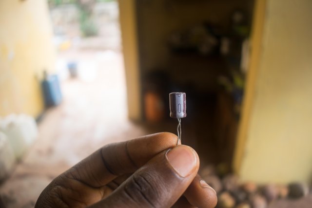
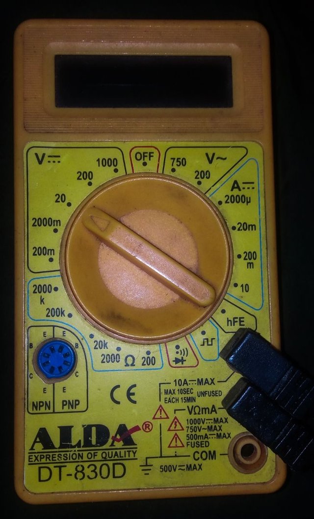
A capacitor is a two terminal electronic device that stores electrical energy in form of charges. The longest terminal for new capacitors are usually the positive terminal and the shortest terminal is the negative terminal. How ever if it is not a new capacitor, the negative terminal has a negative mark beside it. To test if our capacitor is still good we are going to use our multi meter following the steps listed below; 1. We are going to set our multi meter to continuity
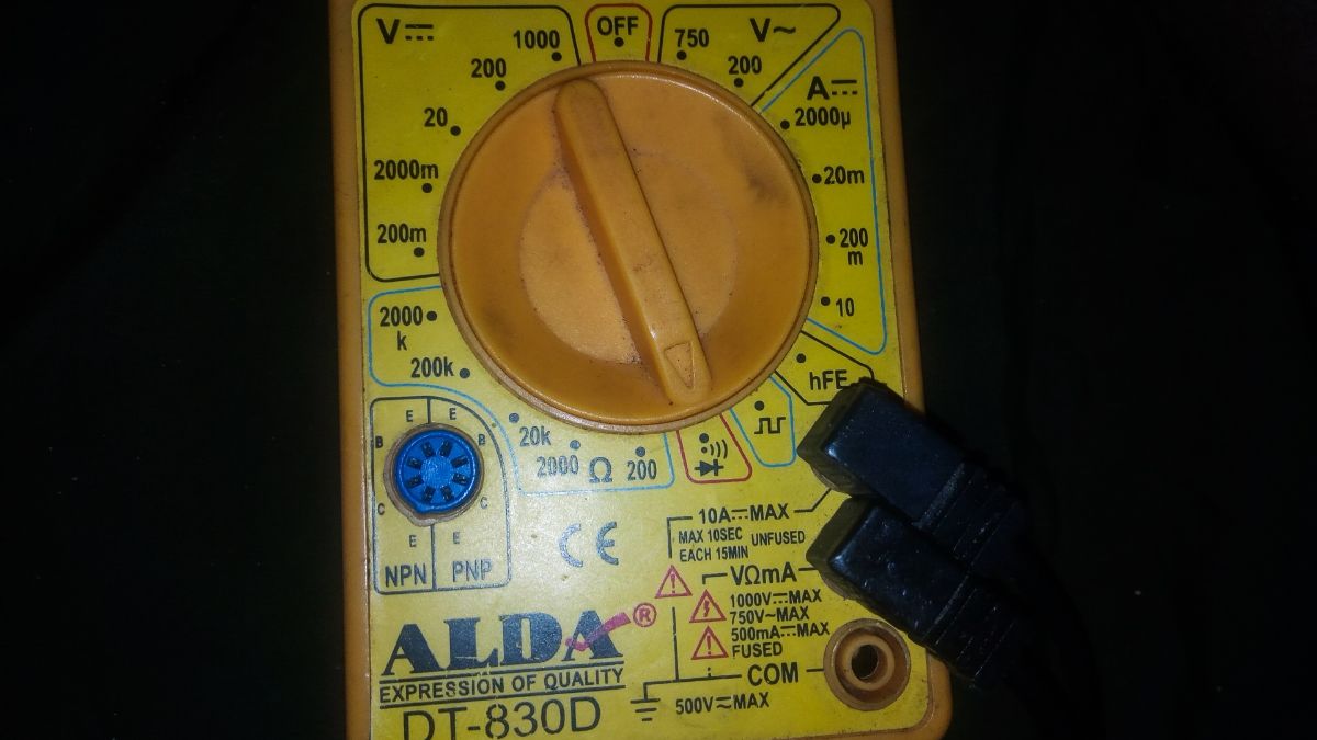
2. We will now connect the positive probe of the multi meter to the positive terminal of the capacitor, and the negative probe of the negative terminal of our capacitor, and wait for at least 8secs. 3. After step 2 above we are going to set our multi meter to 20 volt DC, and connect the positive probe of our multi meter to the positive terminal of our capacitor, and after which we connect the negative probe of our multi meter to the negative terminal of our capacitor.
If our capacitor is still good, the voltage reading on the multi meter will begin to drop, which tells us that our capacitor is still very good, If not the capacitor is faulty.
3. Light Emitting Diode (LED)
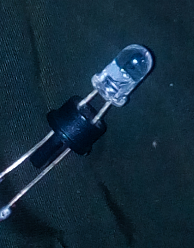
Light emitting diodes are another kind of diodes which when forward biased emits light. When we say forward biased it means that, we are going to connect the positive terminal of our led to the positive terminal of our power supply and the negative terminal of our Led to the negative terminal of our power supply. For a brand new led, the longest terminal is usually the positive terminal and the shortest terminal is the negative terminal. But however, we can not depend on that method. In other to be accurate when testing for the polarity of our Led, we are going to use our multi meter. 1 We are going to set our multi meter to continuity 2 Connect the probes of the multi meter respectively to the terminals of the our Led. 3 If the Led is a good one, it would come on and if not it is faulty.
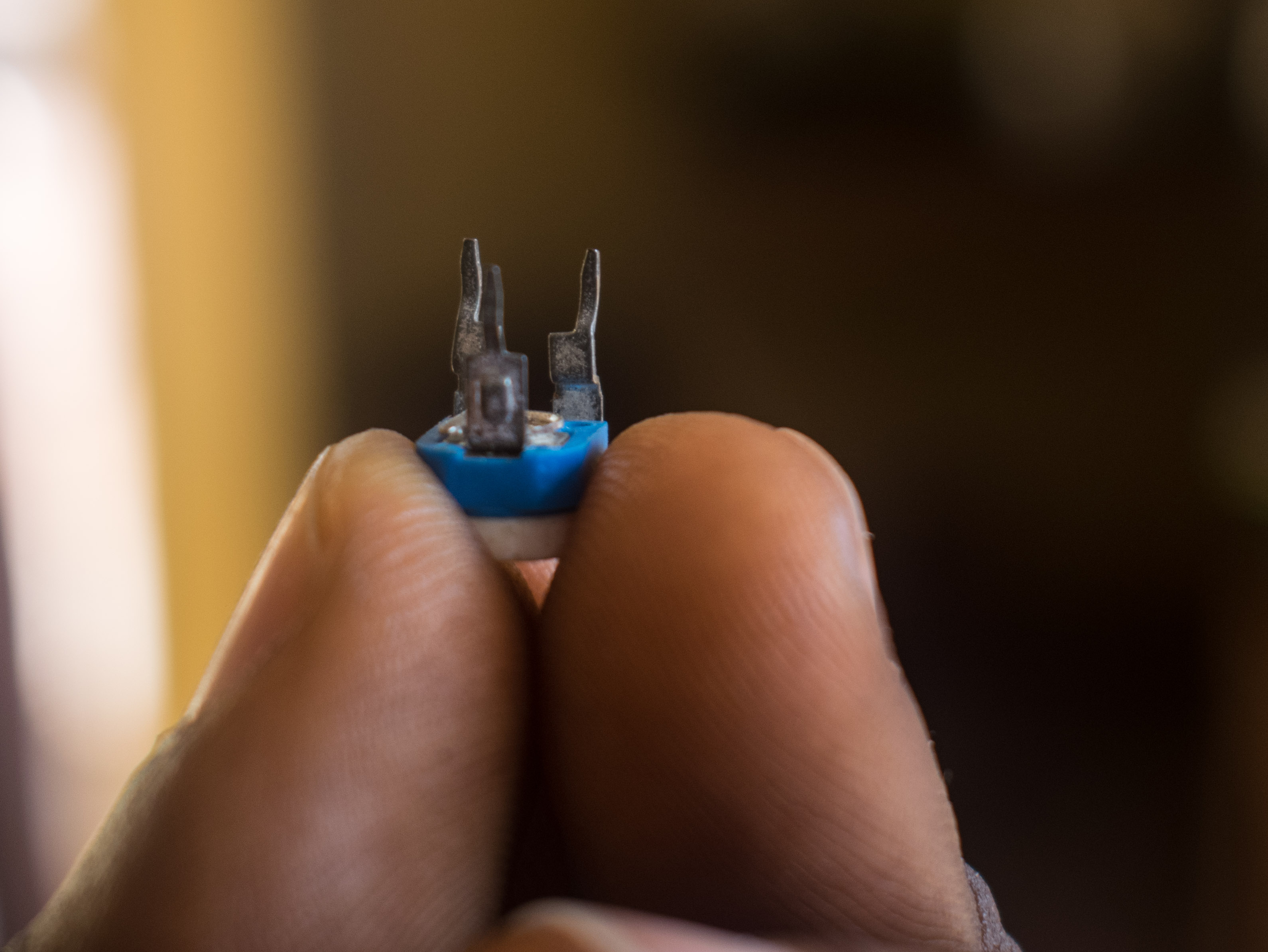
4. Resistor
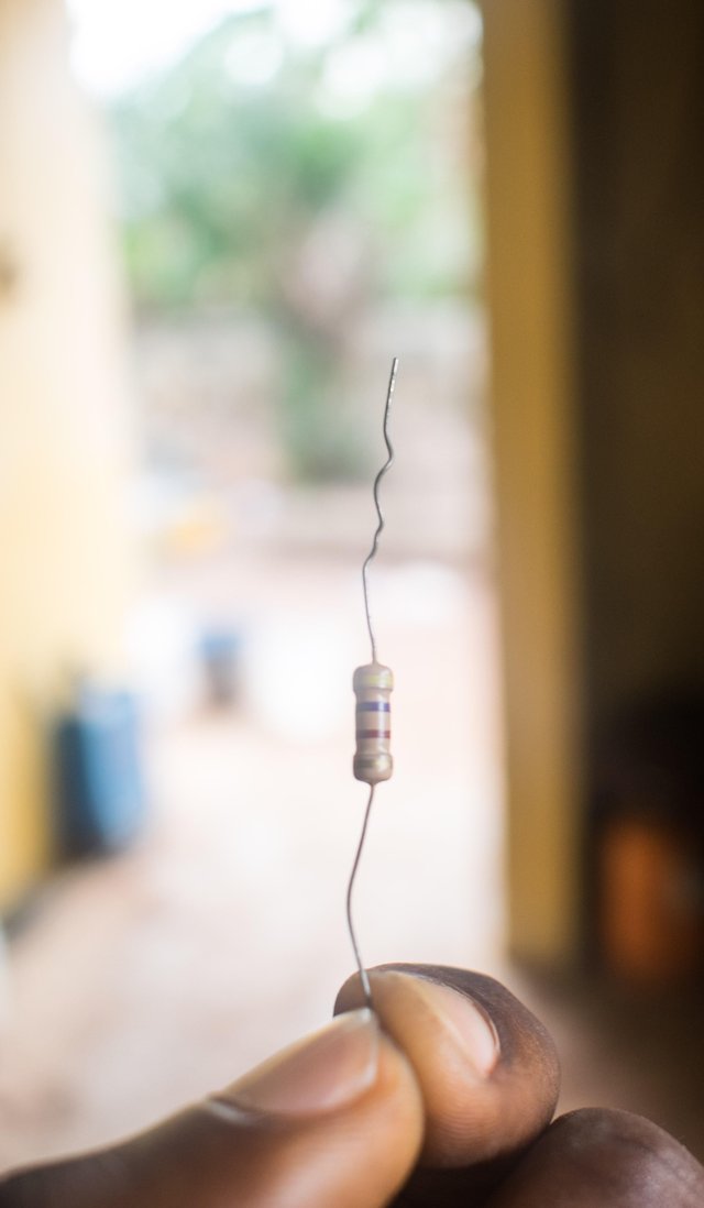
Resistors are devices used to limit the flow of current. Let's use this illustration, imagine you want to open a tap, the more you turn the tap knob in the open direction, the more the water that flows out. Now let's call the flow of water current, and let's call the tap knob resistor. The higher the value of the resistor, the lower the flow of current. And the lower the value of the resistor, the more the flow of current. We have two kinds of resistor; 1. The fixed resistor (like in the image above) 2. The variable resistor.

Under the fixed resistor, we have the 1. Through hole (the one above) 2. Surface mouth.
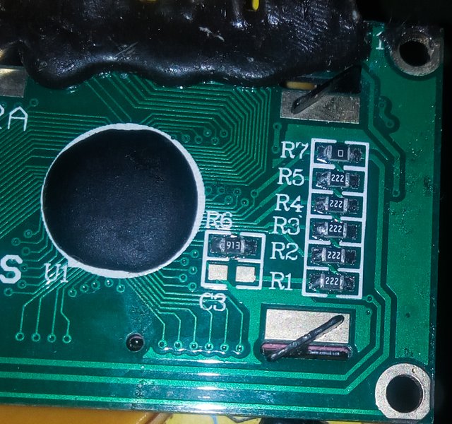
For this post we are going to be using a fixed through hole resistor. Resistor may have their values written on them or they might be placed on them using colour code. These colour coded are placed in bands on the body of the resistor. For a 3 band resistor, the third band is usually the multiplier, for a four band resistor, the fourth band is usually the multiplier. Below is the colour code for various bands of resistors. Resistor do not have polarity.
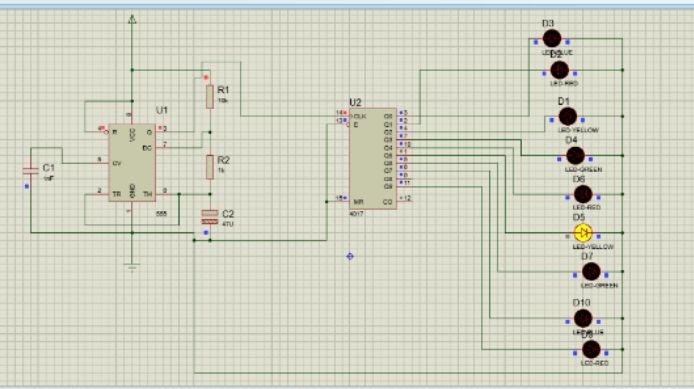
NE 555 IC
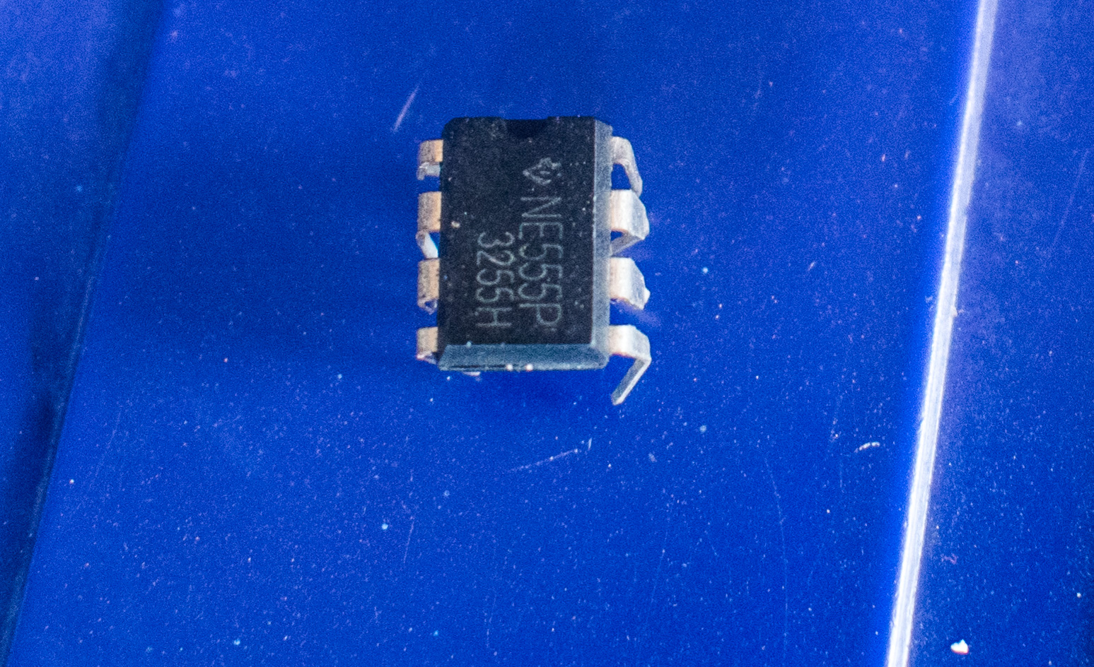
The NE 555 IC also known as the 555 timer, is an integrated circuit chip that helps to provide timing or pulses in circuits. It has eight pins namely; Pin1 as ground. Pin2 as trigger. Pin3 as output. Pin4 as reset. Pin5 as control voltage. Pin6 as threshold. Pin7 as discharge. Pin8 as supply voltage. The 555 timer IC can be operated on various three modes namely; 1 Astable mode. 2 Mono stable mode. 3 Bistable mode. For our circuit we are going to be using it in the astable mode. In this mode, the 555 timer IC gives an output that switch high and low continuously. The frequency at which the output of the 555 timer switches is dependent on C1, R1, and R2. Hence it can be adjusted using the formula F= 1/[0.7 × (R1 + 2R2) × C].
CD 4017 IC
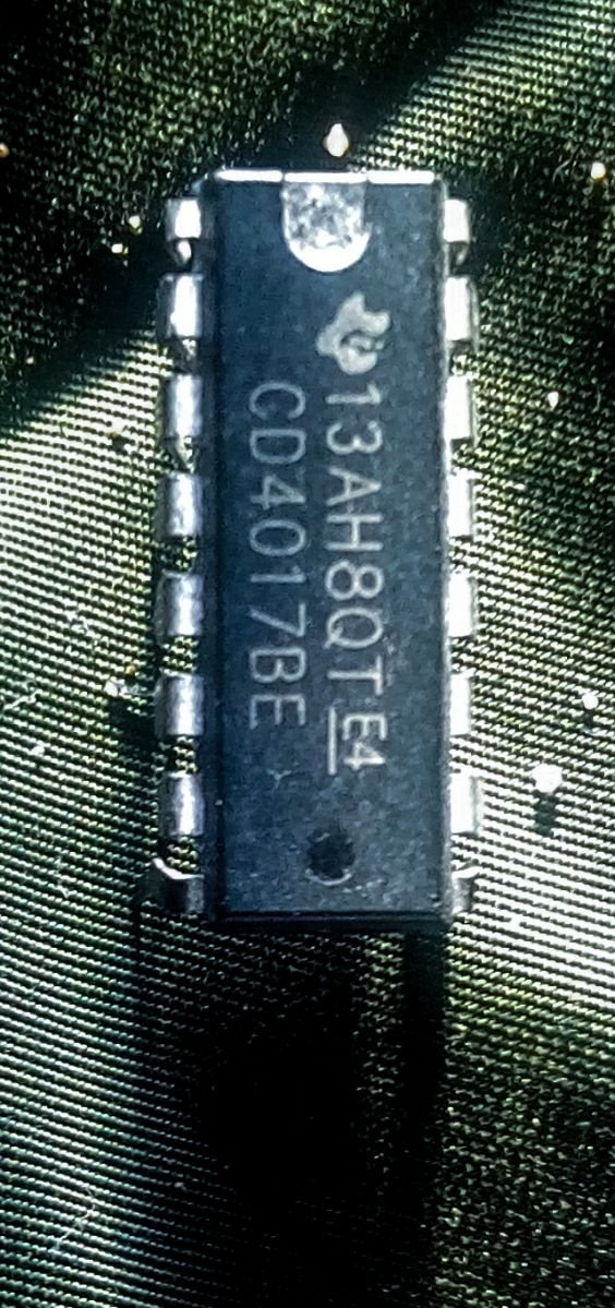
The CD 4017 IC, is a 16 pin CMOS decade counter IC, with 10 output pins. The IC receives a clock signal and produces a sequential output from Q0 to Q9. The pins of the CD 4017 IC are. Pin1 as Q5 Pin2 as Q1 Pin3 as Q0 Pin4 as Q2 Pin5 as Q6 Pin6 as Q7 Pin7 as Q3 Pin8 as GND, VSS(ground) Pin9 as Q8 Pin10 as Q4 Pin11 as Q9 Pin12 as carry out Pin13 as clock enabled Pin14 as clock Pin15 as Reset Pin16 as VDD (power supply)
connection of the circuit proper
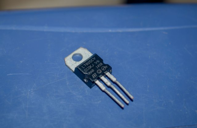
For our circuit we are going to be using a 5 volt power supply. If you don't have one no worries an AAA 9 volts battery can serve as a power supply, but when using it we will have to pass it through a 7805 voltage regulator, to give us an output voltage of 5volts.
For our circuit, we shall be connecting pin one to ground (which is the negative terminal of our battery). After which we are going to connect pin eight and pin four together and take them to the Voltage supply. Pin four is active low, meaning that for our circuit to function, we must take pin four to high, that is we must take it to the supply voltage. Pin five which is the control voltage is connected to ground via a 0.01uf capacitor(remember, ground is the negative terminal of our voltage supply). We used a capacitor in other to filter unnecessary noise. Pin two and six are connected together.
Now we are going to take our 10k(colour code; black, brown, orange and gold) resistor, place one of its end on pin eight (remember pin eight and four has been connected together) and the other to end of the resistor is connected to pin seven.
2 We are going to take our 1k resistor, connect one of it's end to pin seven, and the other end of the resistor to pin six (remember, pin six and two must be connected together).
3 It's time to connect our capacitor. For this circuit we are going to be using 47uf capacitor. We are going to connect the positive pin of the capacitor to pin six and the negative to ground. So that's it! We have been able to generate a clock for our CD4017 IC. We can test out the clock circuit by connecting an LED to pin3. If we are correct, the LED will come on and go off continuously.
clocking our 4017 IC

Before clocking our 4017 IC, we have to make some necessary connections down. Pin 15 of our 4017 IC is connected to pin 13, they are both then connected to pin 8 which is ground. When we are connecting our LEDS, we must take care to make sure they are connected sequentially from Q0 to Q9, if not the LEDs will not countin a sequential order, but in a random manner. Once we are done connecting the LEDs, all we have to do is to connect pin 3 of our 555 timer IC to pin 14 of our CD4017 IC. That's it! We have our Christmas light chaser. Thanks for reading, if eventually you get stuck, feel free to use the comment section to ask questions. Till my next post I remain your real G @fona. MERRY CHRISTMAS AND A PROSPEROUS NEW YEAR!! All images where taken with my Nikon D5300 DSLR camera and my tecno l8 lite phone.
This is a simulation on What you should expect after building it.
Even though I may not fully understand these engineering terms. I find this really awesome. I could see the rapid transition of the lights on the screen. Keep educating us man. Thumbs up.
Thanks very much @asaj