Biomechatronics Intro: Simple Lasercut Rack & Pinion Mechanism
Long time no Steem!
My last semester has started, and it's overwhelming. Some degree of a job hunt is also underway, so that adds to madness.
What'd you learn in school this week?
This year, I am taking a class called Biomechatronics, a field that combines biological signals/inputs with electronic and mechanical parts to get information or to actuate a response. Examples include left ventricular assist devices implanted into a patient's chest to help the heart pump or prosthetics that use information from the residual limb to move.
This prosthetic device uses an armband to collect contractile information from muscles in the limb to deduce the patient's intended motion.

This week, we stuck to the basics: Gears
The basic concept is that you have one gear that drives the motion (this is technically called a pinion) and a second gear (that is actually called a gear) that is pushed or driven by the pinion.
The pinion drives the motion (and is often smaller) while the gear is being driven.
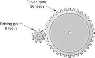
Some gear terminology we covered included the "pitch circle" or the circle along the curve of the gear that represents where the gear and pinion will come in contact. We also talked about "undercutting," the narrowing at the base of a gear tooth that prevents interference.
The plotted contact points between two gears follow the pitch circle (turquoise lines). The red line tangent to the circles is the pressure angle; most gears have an angle of 20 degrees. Notice that below the faint purple line, the teeth of the gears get narrower. That's the undercut.

Homework: Building a Gear Mechanism
After this lecture, the assignment was to make a rack and pinion. In this simple mechanism, when an unrolled gear (the rack) is pushed forward, the real gear rolls along the track.
In the rack and pinion mechansim, the gear (pinion) rolls along the track (rack).
Using gear templates provided in SOLIDWORKS (a software used for designing 3D parts), I adjusted the parameters of the rack and pinion, including the number of teeth and the size of the parts. Then, I determined the height above the rack that the pinion needed to sit at and laser-cut all the parts to make a functioning mechanism.
In laser-cutting, a laser runs along a set path (based on what I designed in SOLIDWORKS) to cut out a pattern on big sheets of stock material.
To assemble the parts, I used a method called press-fitting, where you laser-cut pieces with such precision that they just barely and tightly fit together — no glue, tapes, or screws.
To calculate the height between the bottom of the rack and the center of the gear (or the mount distance), I used the rack height, the distance between the tooth and the pitch circle, and a value called the module that indicates the size of the gear teeth and pitch circle.
After 6 hours of designing the parts and 3 hours of laser-cutting and assembling, I got...
My Adorable Rack and Pinion Pinching Crab Claw
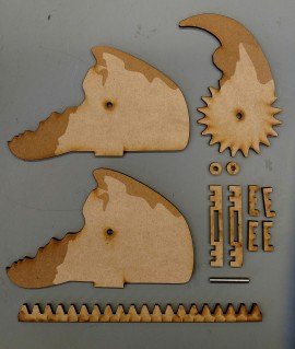
Here are all the laser-cut pieces before assembly. I used a dowel pin (silver) as the axle and two small circular stops to prevent the pin from falling out. I cut all the pieces out of medium-density fibreboard (MDF), a material made of wood residues bonded by heat and pressure. The six smaller parts above the pin make up the base.
My rack and pinion claw in action after press-fitting the parts together. All I have to do is push and pull on the rack to rotate the pinion and move the claw up and down.
I am really excited to see how we will implement simple mechanisms like this one into larger systems. For example, a motor can be added to turn the pinion to translate the rotational motion into linear motion in the rack. Also, the final project for this class is to make a gripper that can pick up and transfer an egg without human interaction, and my professor showed us a video that nicely illustrates how gears can come together to make one!
A four-bar linkage gripper uses two regular gears and a worm gear (the small one between the two other gears) to move the links and hold something between them.
Thanks for reading!
I'll share more from Biomechatronics as we start adding the 'bio' and 'tronic' parts to it, including the robotic egg gripper for my final project.
(That is, if the class leaves me with enough time to do so.)
Join us on #steemSTEM / Follow our curation trail on Streemian
Thank you for this very interesting article that we took a great pleasure to upvote. Please visit our chat channel for more interactions with us!
The steemSTEM project is a community-supported project aiming to increase the quality and the visibility of STEM (STEM is the acronym for Science, Technology, Engineering and Mathematics) articles on Steemit.
Thank you so much for the support @steemstem!
Wow this is a good read. Will you create later a more complicated system than the rack and pinion claw? I'll wait for your next post! Stay amazing :)
Yes! For the final project, I will definitely need to combine lots of gears to make a functional gripper. The gripper will also be able to respond to readouts from electronic components (like pressure/force sensors) on the ends of the grips.
Thanks for the encouragement :)
Cool. I'll wait for that gripper of yours. Nyahaha.
Awesome post @jshmu, looking forward to more :)
Wow. You get to do some really fun and cool things in your class. I can't wait to see your post on the final project on here too (no rush though). Keep posting!
Thanks @stats-n-lats! Haha it'll be months until I even think about that, but glad you're looking forward to it :)
Cool stuffs. Good luck to your future projects. :)
Thank you @zararina! I think I'll need it
Congratulations @jshmu! You have completed some achievement on Steemit and have been rewarded with new badge(s) :
Click on any badge to view your own Board of Honor on SteemitBoard.
For more information about SteemitBoard, click here
If you no longer want to receive notifications, reply to this comment with the word
STOPCongratulations @jshmu, this post is the second most rewarded post (based on pending payouts) in the last 12 hours written by a Dust account holder (accounts that hold between 0 and 0.01 Mega Vests). The total number of posts by Dust account holders during this period was 3382 and the total pending payments to posts in this category was $913.78. To see the full list of highest paid posts across all accounts categories, click here.
If you do not wish to receive these messages in future, please reply stop to this comment.
Wow thank you :)