Inside a cheap electrical Multimeter
Last week I found a coupon for a free multimeter at Harbor Freight. If you don't already know, a multimeter is one of the most basic electrical tools, and lets you measure voltage, current, and resistance, along with some functions like figuring diode voltage drop and the gain of transistors.
I already have one, but I like having a cheap one that I can break if needed. My last sacrificial multimeter died an unfortunate death when 35,000 volts arced across the resistors I was using to safely read the voltage and destroyed the meter. The Harbor Freight one will make a nice replacement. While you can actually get them for effectively 50 cents (by buying a cheap folding knife at the register and using the coupon), I needed new gloves anyway so I purchased some and threw in the meter for free with the coupon.
So, naturally, I've decided to take it apart and see what's inside.
Quick Overview
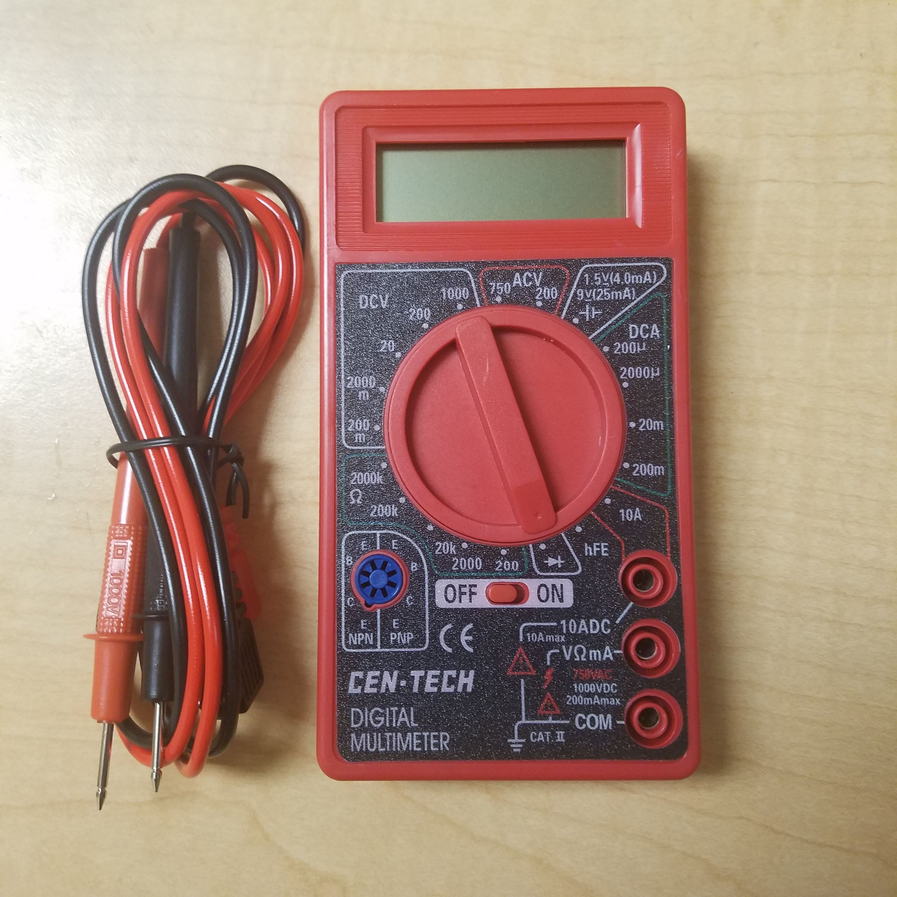
Let's first go over what this meter can do. If you're just getting into electronics as a hobby, you really need to buy a multimeter, although a slightly better quality one might be a better bet.
Turning the knob changes the setting. The DCV setting lets you measure constant voltages. This is useful for checking batteries or just measuring parts of a circuit. ACV lets you check high voltage alternating-current lines, like the wall outlets in your house for example. I personally have never trusted the little probes enough to actually stick them in the wall and don't plan on using this setting. DCA lets you measure much smaller direct currents, and can be useful for measuring stuff like solar cell outputs.
The self-explanatory Ω setting lets you measure the resistance of just about anything. Finally, we have a diode tester (marked with the diode symbol) which gives you the forward voltage of a diode (around 0.7 volts for silicon diodes). This can also be used to test diodes like LEDs and light them up for you to view the color. Next to this is the HFE setting, which measures the gain of a bipolar junction transistor (basically how much current you get across the main channel when a small current is applied between the base and emitter). To use this setting you have to plug a transistor into the blue circle to the left.
Okay enough of that, let's see inside.
Opening the multimeter
This device is incredibly easy to open, probably because they expected the user to replace the included 9 volt battery. Two large screws hold down a large red plastic backplate. Once these screws are removed, the plate pops right off and reveals the internals:
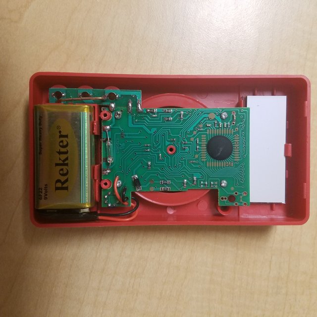
Quite a sparse board! Here we can see a few surface mount resistors/capacitors, a moderately sized surface mount M7 diode, what appears to be a glass fuse on the left, and a sealed in controller circuit. Four screws hold the board down to the front panel.
I did actually remove these screws, but found that the board doesn't want to be removed from the plastic housing because it is held down by the three probe connectors. Removing these could damage the device, and I don't like permanently destroying things, so I left it in place. I could still see behind the board, and saw nothing of note: There aren't any components visible on the other side. What it does contain is a large circle of metal traces that lets the knob work. The knob contains metal plates that short various traces when turned, giving instructions to the controller on what setting to use.
Here's a closer look at the central controller:
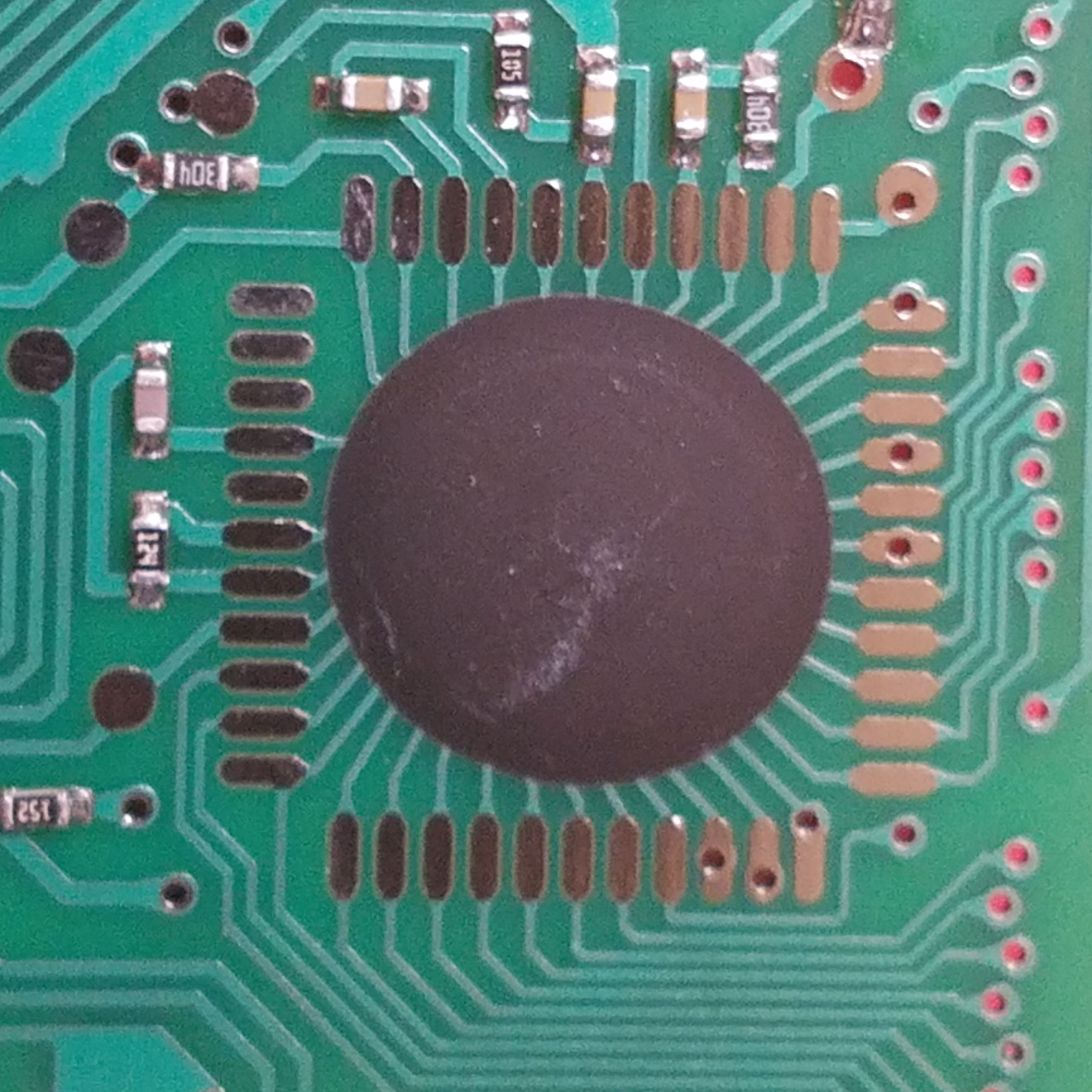
There's some sort of IC chip under here but it's impossible to see. You can see all of the traces leading into a very hard, sealed black circle. It seems the manufacturer totally sealed in the only integrated circuit on this multimeter. This is probably to prevent reverse engineering if I had to guess. I've seen this a lot on dirt cheap calculators as well, so perhaps there is a functional reason to do this.
The black coating is very hard, and I don't really want to scrape it off, so the insides will remain a secret for now.
Let's take a look at the display. This display is a liquid crystal display (LCD) that can display several digits with no backlight. It isn't actually wired to the circuit, and is connected via pressure from the connectors on the back of the circuit board when it is screwed in. I removed the screen to get a better picture:
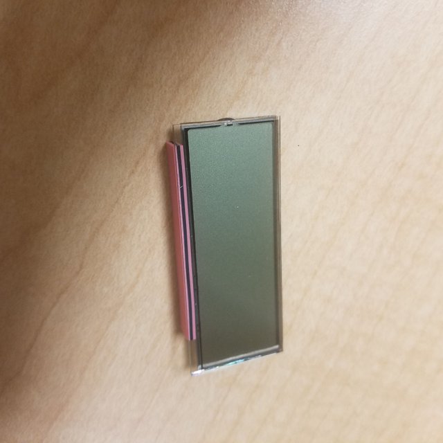
The pink foam part is what connects the screen to the circuit. This screen can easily display numbers without consuming much power, and as such serves as a great low cost option for this meter.
On the bottom of the circuit is what appears to be a glass fuse. Here's a closer look:
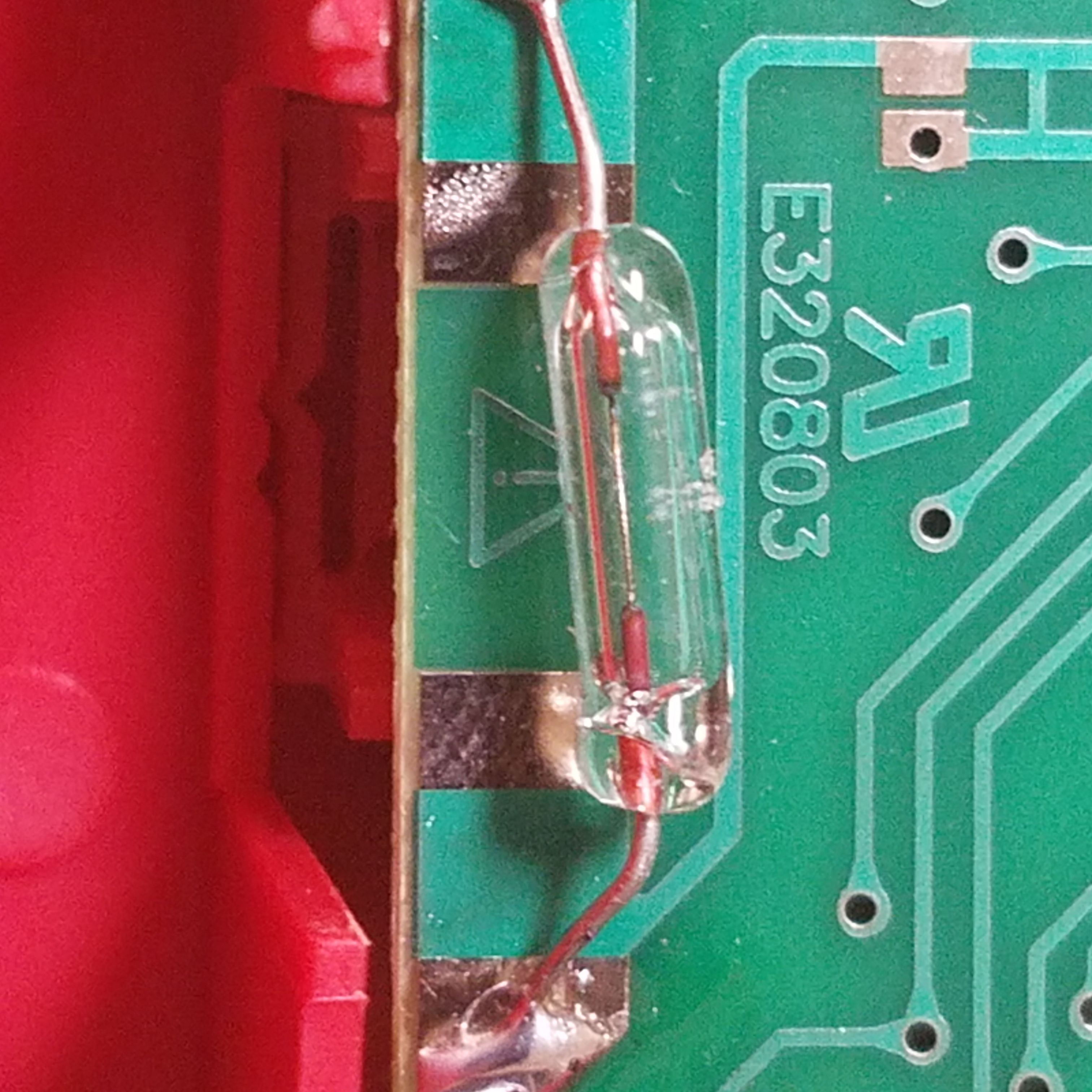
The likely fuse connects the low-current input to the rest of the circuit. This is a protection device. If current greater than the rating for that port (200 mAmps) were to flow in, it would destroy part of the meter. To prevent this, the fuse is put in place. A fuse acts like a wire, but is set to destroy itself once a certain current is reached. If 200 mA flows across the fuse, the tiny wire inside will melt, breaking the connection and shutting off current to the meter. This means that if you put too much current through the port, it will destroy that port but won't destroy the meter itself.
Strangely unlike many meters this fuse isn't removable. I suppose this was to save cost. Ordinarily you would be able to pop the fuse out and add a new one in the case of a failure. However, I suppose it wouldn't be too hard to solder in a replacement if it gave out.
Sadly that's about it for components of note. The only other slightly noteworthy component here is a M7 diode:
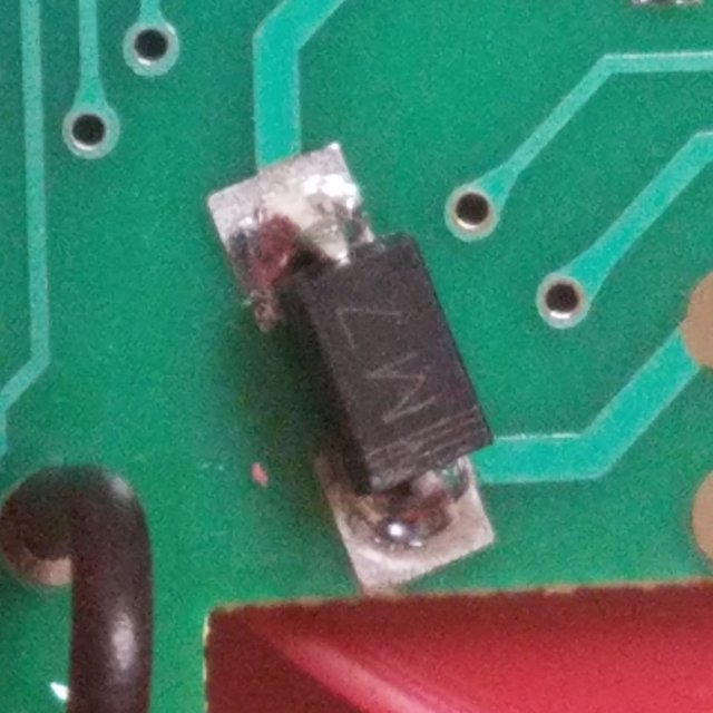
The white bar indicates polarity (the bar is the cathode). This M7 diode only lets current flow in one direction. At its maximum rated current of 1 amp, 1.1 volts will drop across this diode. Sadly I really don't know what's it for, and I'm not sure how to find out without getting inside the black coating covering the IC.
Conclusion
That's about it for this multimeter. I'm sure the device is unreliable and I wouldn't trust it to carry high voltages with me holding it, but when you can buy it for 50 cents I can't really complain. If you want to start getting into electronics, your first purchase should be a multimeter.
Let me know if you have any questions. I apologize for not being able to get a little more in-depth here, but the sealed in controller chip makes things difficult.
Thanks for reading!
All images in this post are my own. You are welcome to use them with credit.
Being A SteemStem Member
Where is shunt resistor?
Ah I should have found that for the post, thanks for bringing it up. It looks to be the 1-ohm (1R00) resistor on the middle right with the poor solder job, as this could straight through the trace for the high current port. However I could be wrong, as I was expecting a lower value.
Next, will we analyze the oscilloscope?
I have half a dozen of these cheap Multi-meters I can send you (none of them work)!
No need, since now I know I can get more from Harbor Freight for 50 cents when they break :)
How did you end up breaking up yours? The only redeeming quality of this devices seems to be their cost.
I have collected different cheap types over the years..I keep meaning to buy a Fluke. They all seem to die with a short span of time.
hey @proteus-h you explains very small technicalities about the technology which is a great thing thanks for sharing.
I have seen quite a few multimeters with removable fuses (which seem to break quite often when students use them to measure something in chemistry), and I don't think many would be able to remove and resolder a new one that easily.
That would certainly completely break this tool for many people ...
But I have a question regarding these mutlimeters ... we have a few electrochemical reactions producing voltage (but almost no current), and we noticed something: When changing the range of measurement from, I think it was 1000 mV to 10 V, we noticed something odd: On the first setting, the device recorded 930 mV (close to the max), but on changing to the higher setting, it displayed 0.6 V, dropping the measured value by almost half.
This was really perplexing ... as it happened with more than one device ...
To be honest I'm not sure what's causing that. My best guess is just that the meter is very low quality and as such is quite inaccurate.
As for the fuse, I agree - it's very easy to breach 200 mA and blow the fuse. Another victim of the meter's extremely low cost I suppose.
Uhhhhh.... I used to own one of those. I blew it, while measuring 30V DC. Never again. Even UNI-T cheapo-meters has some input protection, even a PTC will help.
electronic circuit is most important of the our world