Logic circuit using "Logisim" (Sequential circuit)
I am a student of electronic engineering from the Simón Bolívar University of Venezuela (USB), a few quarters ago I was studying the subject "Digital Circuits" where we were evaluating the design of logic circuits through different simulators including the simulator "Logisim" . One of our evaluations was to design a sequential circuit to understand its management and its possible applications. For this we were assigned an activity that consisted of the design of this circuit to meet the specifications given by the teacher.
Objective:
Design and understand the operation of a state machine through the use of Flips Flops and logic gates.
Design and results:
Future State integrated circuit:
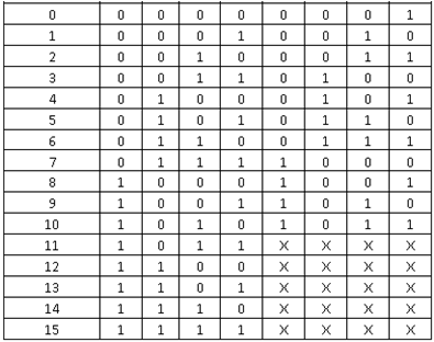
In this circuit the change is made from the current state to the future state in binary coding. The output of each flip flop works as a counter for each state of the circuit, they reflect the number of the current state of the circuit in binary coding. Due to the specifications, a certain output for 11 states is reflected, so the numbers from “0” to “10” are reflected in binary coding, with “D3” being the most significant bit.
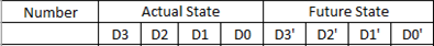
Next, in table 1, the truth table is shown in which the current state is reflected as input and the future state as output of the circuit.
In the next image you can see the resulting combinatorial circuit implemented in this integrated .

The output of each flip flop functions as a counter for each state of the circuit, they reflect the number of the current state of the circuit in binary coding and serves as the input of the integrated circuit "output".
Below is the truth table that reflects the current state in decimal and binary coding next to the desired output for the circuit.
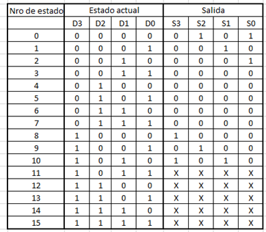
In the integrated circuit "Output", a configuration of logic gates was developed which yield the desired output upon receiving as input any of the 11 states to work.
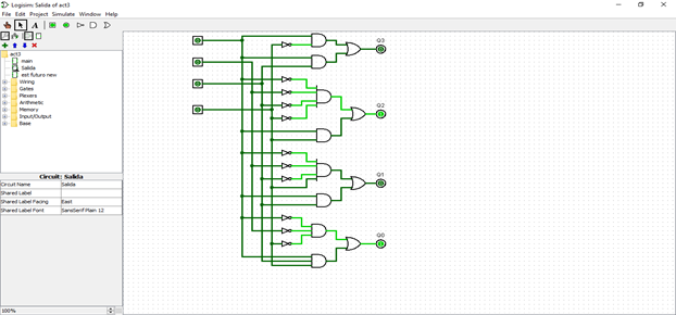
In the same way, in addition to serving as the input of the integrated circuit "output", the number representing the current state works as the input in the integrated circuit "Future State".
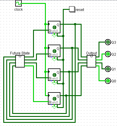
Main Circuit:
At the time of designing the main circuit, each output of the ‘Future State’ circuit was connected to a ‘D’ type flip flop, and in turn, each positive flip flop output was connected to the inputs of that circuit. The functionality of this is that the value of each bit that enters the flip flops is saved to be used on the next clock pulse, in this way, and for the assignment of the outputs that were given in the design of 'Future Status 'a loop is simulated, in which there are only 11 possible states.
Each output of these flip flops was also connected to the ‘Output’ circuit inputs, where each output is connected to a bit that reflects what you want to show in each state. We can see it in Figure3.
The "reset" button performs the function of returning the counter to the initial state and displaying the corresponding assigned value on the output.
Conclusions:
It was possible to design a sequential circuit that reacts differently for each state controlled by the clock which changes the circuit with each pulse.
The use of Flips Flops is essential when storing memory since it retains a previous value and then use it in its output which is the basis of the sequential circuit, when performing the simulation the pattern requested in the output was observed in the output correct for each of the 11 states, with the option of pressing a “reset” button which returns the counter to the initial state and reflects the corresponding value at the output, the designed circuit worked correctly without logic failures Nor the sequence.
References:
Angel Terrones, “Activity 2” delivered on November 2018.
Taub, Herbert. Circuitos Digitales y Microprocesadores. Editorial Calypso. Mexico DF. (1998)
Congratulations @orbital753! You have completed the following achievement on the Steem blockchain and have been rewarded with new badge(s) :
You can view your badges on your Steem Board and compare to others on the Steem Ranking
If you no longer want to receive notifications, reply to this comment with the word
STOPVote for @Steemitboard as a witness to get one more award and increased upvotes!