Improvised Worm Drive
I previously discussed how to make gear teeth when you don't have add-ins for gears in your CAD software:
https://steemit.com/cad/@steampunkkaja/improvised-gears
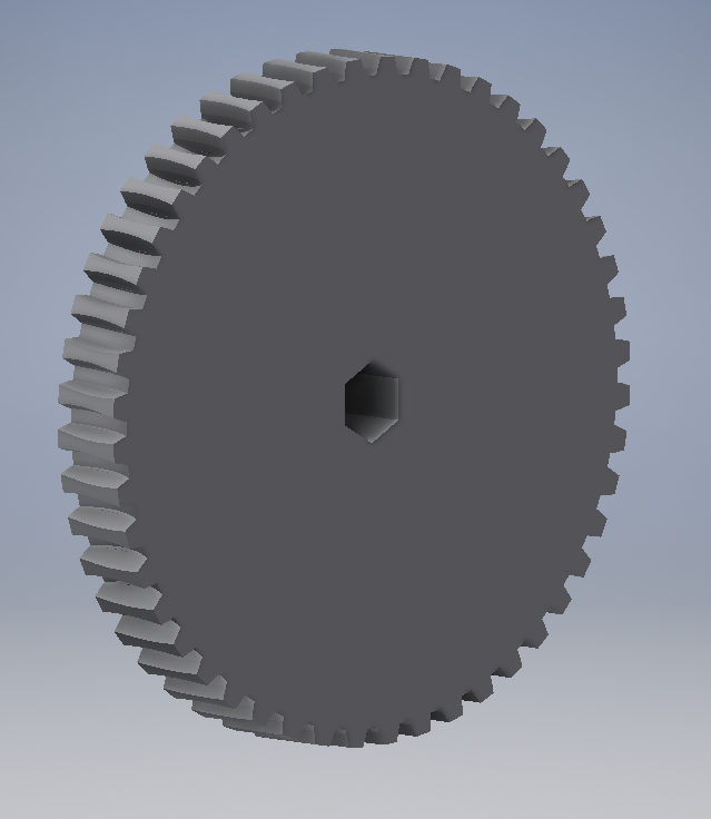
This time, however, I will show how you can actually put these things to work, instead of making a decorative yet accurate-looking gear. BEHOLD!
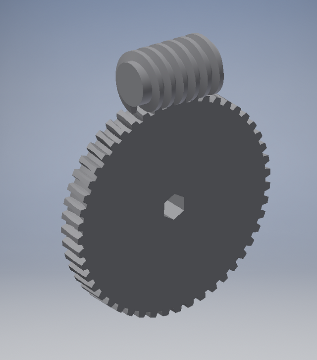
Now, for those who don't know, you can't make a worm drive with an ordinary screw and an ordinary, straight-toothed gear (properly called a spur gear). You need a special type of screw, either a 29-degree (imperial) or 30-degree (metric) acme screw, and a gear that has been hobbed using what is, essentially, a tap for the exact same thread as the worm screw. Now then, my example uses a 29-degree pitch, because I learned nearly everything I know about machining in the U.S. This, by the way, is where the bizarre 14.5-degree pressure angle comes from. Anyway...
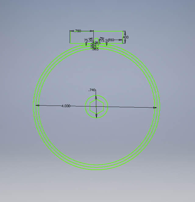
Step 1: begin with a drawing used for both parts. You'll see why very soon:
Step 2: make the worm
I found it easier to make the thread first, and then the core. By the way, you'll notice that the tooth/thread profile is mirrored. There are two reasons for this. First, you will need it in both directions. Second, Autodesk Inventor always uses the EXACT CENTRE of the profile as the pitch diameter when creating a coil. Therefore, you need to use BOTH SIDES of that mirror profile in order to get the proper results. This goes for any coil, including "ordinary" V-threads.
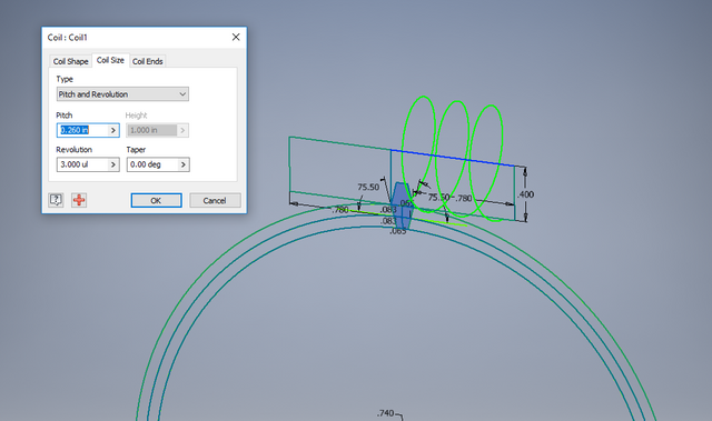
As you may have noticed, the coil goes in only one direction. I had to create two of them in order for this to work. Anyway, the worm screw is done, aside from any shafts, bores, or keyways that you may wish to add.
Step 3: cut the first tooth profile in the gear
This is, in principle, much like my improvise spur gear. The difference is that you create a negative coil, rather than a positive one (in other words, cut don't add - it still coils in the same direction).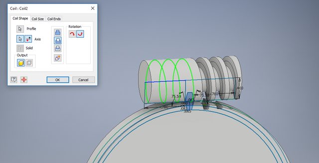
As you can see, one coil is already cut, this is the second. You don't HAVE to put the tooth profile right in the middle and make two coils, by the way, you can move it off to the side in your drawing.
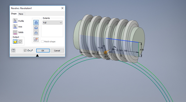
Step 4: array and wait
Because you're making a circular pattern of a coil (or two), this will take the computer a while. I didn't time it with a stopwatch, but it was probably a full minute. That's for a 48-tooth gear. 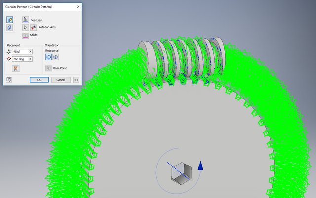
Now, I have the worm's core here only for illustrative purposes. If you extrude the gear blank, then create the coil for the tooth profile, you won't have anything left to trim when you're all done:
If anyone shows interest, I may make a more complicated version of this in the future for one of my video CAD tutorials.
Congratulations @steampunkkaja! You have completed the following achievement on Steemit and have been rewarded with new badge(s) :
Click on the badge to view your Board of Honor.
If you no longer want to receive notifications, reply to this comment with the word
STOPTo support your work, I also upvoted your post!