Introduction To Basic Logic Gates
What are Logic Gates ?? Types of Basic Logic Gates and the and there logical expressions .
In electronics, a logic gate is an idealized or physical device implementing a Boolean function; that is, it performs a logical operation on one or more binary inputs and produces a single binary output 0 , 1 . (0) represents the low output and (1) shows the output is heigh
There is three basic gates.
- OR Gate
- And Gate
- Not Gate
OR Gate
OR gate is an electronic circuit in which the output will heigh (1) if both inputs are heigh or one of the given input is heigh(1) and the output will the low (0) if both the given inputs are low (0).
The OR gate is represented with the (+) Symbol
Logic Expression
Y = A + B
Example

In this Truth table you can check it out that both the inputs ate Low (0) then the output is low (0) and if any of the input is heigh (1) then the output is heigh (1)
Diagram of OR Gate
OR Gate is represented by the diagram given below
And Gate
And Gate is an electronic circuit in which output will be heigh (1) if only the both inputs are heigh (1) and if any of the input is low (0) then the output will be low (0).
The And Gate is represented by the (.) dot symbol
Logic Expression
Y = A.B
Example
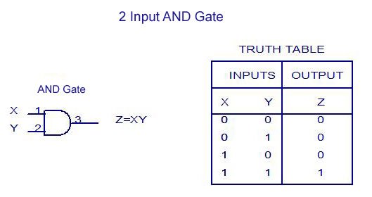
In This Truth table you can check out the output is heigh (1) when both the inputs are heigh (1) and the out put is low (0) when any of the input is low (0).
Diagram of And Gate
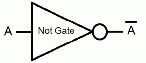
Not Gate
Not Gate is known as invertor. In This electronic circuit the out put will be high (1) if the input is low (0) . If the out is heigh (1) then the input will be low (0).
Logic Expression
A = ^A
Example
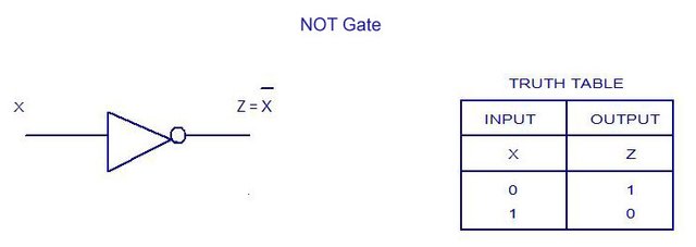
Diagram Of Not Gate