Tutorial Basic - How To Make Ladder Diagram Using CX-Programmer
What Will I Learn?
- You will learn how to use CX-Programmer
- You will learn how to create a direct on line circuit
- You will learn to create a program to run a PLC
Requirements
- You need a basic understanding of CX-Programmer apps.
- You need an understanding of basic electrical circuits
- You need an understanding of the function keys on the app
Difficulty
- Basic
Tutorial Contents
On this occasion I will make a tutorial on how to use CX-Programmer application to create ladder diagram, because many people say that making ladder diagram in CX-Programmer application is very difficult. usually CX-Programmer application is used to create a program that will be included in the PLC, by making ladder diagramnya using CX-Programer application, after the ladder diagram is completed then the ladder diagram can be simulated directly on the CX-Programmer application. and the steps you need to do are as follows:
The first thing to do is enter or open a pre-installed CX-Programmer application by clicking on the CX-Programmer application icon on your computer's desktop.

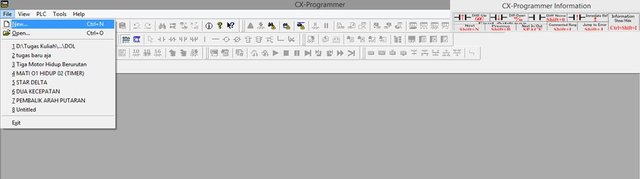
Once entered in the CX-Programmer application, the next step to do is to create a project by clicking on the file menu on the top left of your computer and then click the new menu, as shown below:
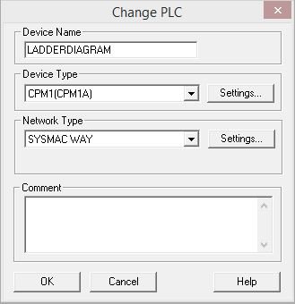
Then the display will appear like the picture below, then we have to fill in Device Name and Device Type. For Device Type we choose CPM1 (CPM1A) because the type of PLC we use is type CMP1A, then click OK.
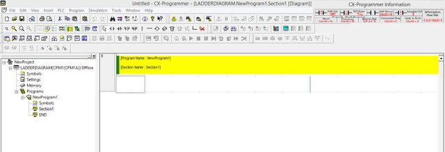
The next step when we go through the stage, we can create a ladder diagram in the window that appears as shown below, where we can create ladder program for PLC to be used.
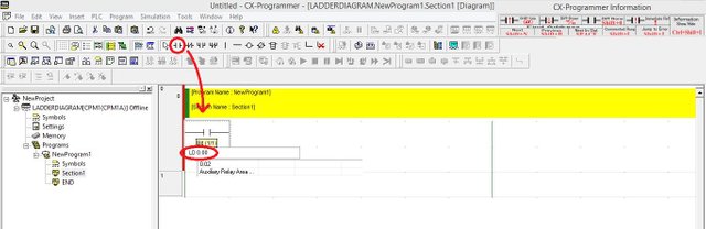
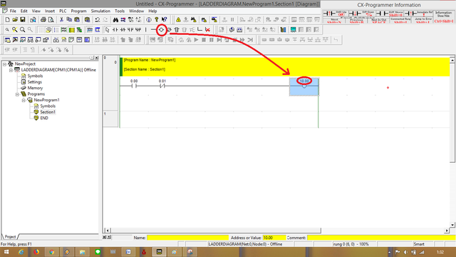
The next step we can begin to create the program we want to run the PLC using the instructions contained in the tool bar.
Then if we want input using NO contact, then choose on tool bar symbol NO contact, then drag the NO contact icon into Rung.
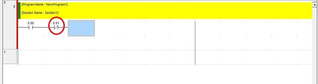
The next step should be to address the contacts we use. Like the picture below :
If you want to add more inputs, such as NC contacts, we can perform the same procedure as adding NO contacts, but for addressing must be adjusted, do not crash, or address the same.
The next step is to add the output on the ladder diagram, we can use the instructions on the tool bar that is already available, and do addressing such as when adding input. can be seen as picture below:
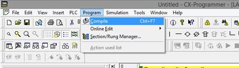
After the ladder program is finished created as shown below. The next step is to compile the project ladder diagram we have created in the way as shown below :
So many tutorials from me, may be useful for all of us.
Posted on Utopian.io - Rewarding Open Source Contributors
Your contribution cannot be approved because it does not follow the Utopian Rules.
You can contact us on Discord.
[utopian-moderator]