Electronic Project 26: How to make a simple traffic light system in a single lane and a pedestrian lane with manual operation
What Will I Learn?
At the end of this tutorial:
♦ The readers will be able to create a traffic light system
♦ The readers will be able to know how the circuit works.
♦ Learn to apply the circuit in real time scenario
Introduction
In this tutorial, we will create a simple traffic light mechanism that could be applied in real time scenario. Here we will program the arduino uno to make a traffic light system in a single lane and a pedestrian lane. At the pedestrian lane, there is a pushbutton that can be used by the people or traffic enforcer to directly activate the pedestrian lights. The switching of lights is only 30 seconds interval, green and red.
Requirements
Electronic Components
♦ Arduino Uno
♦ Pushbutton
♦ LED
♦ Resistor
♦ Breadboard
♦ Connecting wires
Software
♦ Fritzing application
Difficulty
♦ Intermediate
Tutorial Contents
Using the fritzing software, we will create our circuit diagram, arduino codes and prototype using the breadboard
Part I. Schematic Diagram
So first let us construct our circuit diagram.
Select the electronic components needed for the circuit in the fritzing library. We need 1 arduino uno, 1 pushbutton, 6 resistors and 5 LEDs.
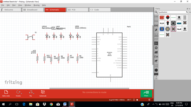
Arrange the components before constructing the circuit.
In arranging the components, place all the components for the input side (left side) of the arduino and the components for the output side (right side).
In this tutorial the input components will be the pushbutton and a resistor. The rest of the components are for the output side.
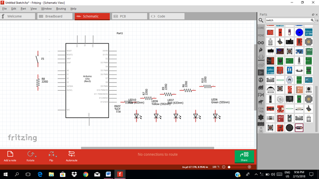
Now let us construct our circuit diagram. At the input side of our microcontroller, we need one input pin for our pushbutton. Since the pushbutton is an analog input, so we will choose the analog inputs of our microcontroller. So in this tutorial I will select the analog pin 1.
The pushbutton will be connected to our 5V source output from the arduino uno and the other terminal is to be connected to the ground resistor.
While at the output side of our microcontroller is the traffic light system which is composed of 5 LEDs. So we need 5 digital output pins, 3 for the single traffic lights and 2 pins for the pedestrian lane traffic lights.
Each output pins must be connected first with a resistor to limit the current flow and to avoid damaging the led.
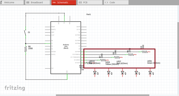
Now we will connect the led base from the single traffic lane and pedestrian lane. At the single traffic lane, 1 Green led, 1 Yellow led & 1 Red led. While at the pedestrian lane, we have 1 Green led and 1 Red led.
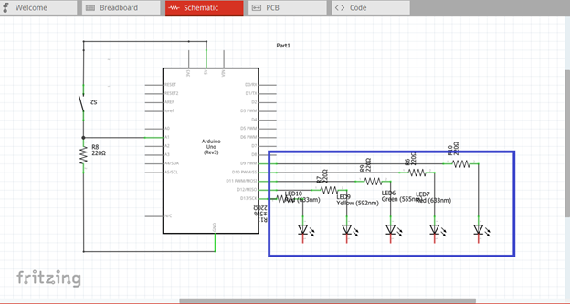
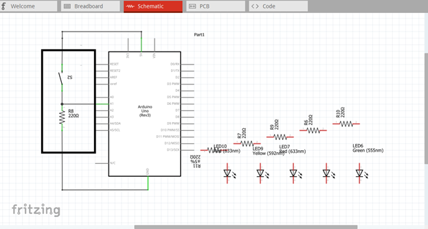
Here is our final circuit diagram.

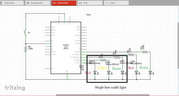
At the single lane traffic light, the time interval between green and red light is 35 seconds. When the light is green (it means go) it is programmed for only 30 seconds, then after 30 seconds the yellow led will start to lights. It means the red led (stop light) is about to occur allowing vehicle to have time to stop. This 30 seconds is intended only for this tutorial, but in the real scenario it is above 30 seconds.
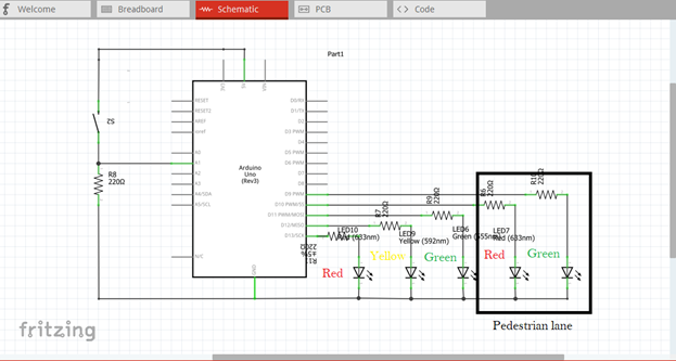
Then at the pedestrian lane, the moment the traffic light turns to red light, it will turn the green signal which means the crowd can now walk through the pedestrian lane and vice versa when light turns to green. The traffic enforcer can manually turns the green or red light at the pedestrian lane using the pushbutton.
Part II. Code
Now let us do programming of our Arduino uno.
Click on code to start.
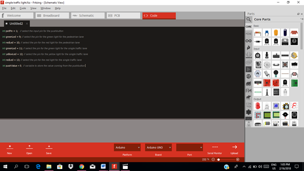
We declare that the input pin of the pushbutton is analog pin 1 and the output pins are pin 9, 10, 11, 12 & 13.
int pushPin = 1;   // select the input pin for the pushbutton
int gpLed = 9; // select the pin for the green light for the pedestrian lane
int rpLed = 10; // select the pin for the red light for the pedestrian lane
int gsLed = 11; // select the pin for the green light for the single traffic lane
int yellowLed = 12; // select the pin for the yellow light for the single traffic lane
int rsLed = 13; // select the pin for the red light for the single traffic lane

int pushValue = 0; // variable to store the value coming from the pushbutton
void setup() {
  // declare the pushPin as an INPUT:
  pinMode(pushPin, INPUT);
// declare the traffic light for pedestrian lane as an OUTPUT:
pinMode(gpLed, OUTPUT);
pinMode(rpLed, OUTPUT);
// declare the traffic light for single traffic lane as an OUTPUT:
pinMode(gsLed, OUTPUT);
pinMode(yellowLed, OUTPUT);
pinMode(rsLed, OUTPUT);
}

void loop(){
changeLights();
delay(30000); }
void changeLights(){
//green off, yellow on for 5 seconds
digitalWrite(gsLed, LOW);
digitalWrite(yellowLed, HIGH);
delay(5000);
//turn off the yellow led, then turn on the red led for 30 seconds
digitalWrite(yellowLed, LOW);
digitalWrite(rsLed, HIGH);
delay(30000);
// red led and yellow led for the single lane is turn on for 5 seconds
digitalWrite(yellowLed, HIGH);
delay(5000);
// turn off the  red and yellow led, then turn on the green led for the single lane traffic light
digitalWrite(yellowLed, LOW);
digitalWrite(rsLed, LOW);
digitalWrite(gsLed, HIGH);
delay(5000);
}

For the pedestrian lane traffic light
void loop(){
If (digitalRead(pushPin) == HIGH){
delay(10);
changeLights();
delay(10000); //wait for 10 seconds
}}

Here are our arduino codes.
int potPin = 1;   // select the input pin for the pushbutton
int greenLed = 9; // select the pin for the green light for the pedestrian lane
int redLed = 10; // select the pin for the red light for the pedestrian lane
int greenLed = 11; // select the pin for the green light for the single traffic lane
int yellowLed = 12; // select the pin for the yellow light for the single traffic lane
int redLed = 13; // select the pin for the red light for the single traffic lane
int pushValue = 0;  // variable to store the value coming from the pushbutton
void setup() {
  // declare the pushPin as an INPUT:
  pinMode(pushPin, INPUT);
// declare the traffic light for pedestrian lane as an OUTPUT:
pinMode(greenLed, OUTPUT);
pinMode(redLed, OUTPUT);
// declare the traffic light for single traffic lane as an OUTPUT:
pinMode(greenLed, OUTPUT);
pinMode(yellowLed, OUTPUT);
pinMode(redLed, OUTPUT);
}
void loop(){
changeLights();
delay(30000); }
void changeLights(){
//green off, yellow on for 5 seconds
digitalWrite(gsLed, LOW);
digitalWrite(yellowLed, HIGH);
delay(5000);
//turn off the yellow led, then turn on the red led for 30 seconds
digitalWrite(yellowLed, LOW);
digitalWrite(rsLed, HIGH);
delay(30000);
// red led and yellow led for the single lane is turn on for 5 seconds
digitalWrite(yellowLed, HIGH);
delay(5000);
// turn off the  red and yellow led, then turn on the green led for the single lane traffic light
digitalWrite(yellowLed, LOW);
digitalWrite(rsLed, LOW);
digitalWrite(gsLed, HIGH);
delay(5000);
}
void loop(){
If (digitalRead(pushPin) == HIGH){
delay(10);
changeLights();
delay(10000); //wait for 10 seconds
}}
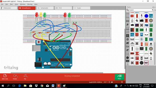
Part III. Breadboard
Click on the breadboard.
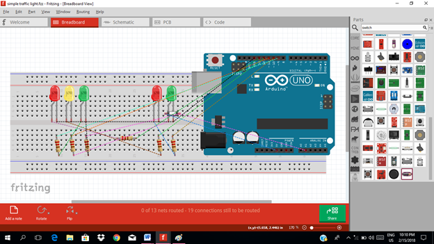
Arrange each component in the breadboard before connecting.
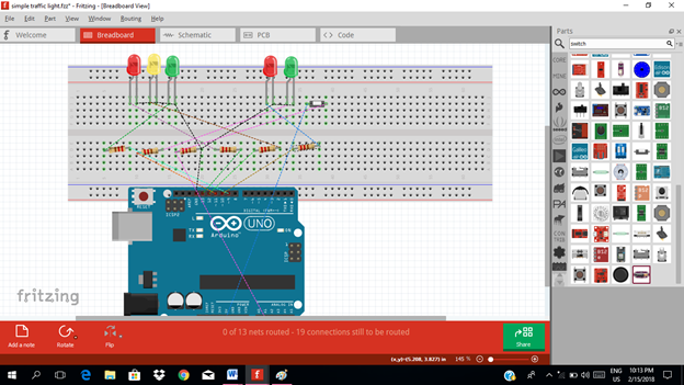
Now connect each component if you don’t know how to connect using breadboard just read my previous tutorial about how to construct a circuit in the breadboard
Application
The readers can create their own traffic light system or a light signal.
Like the example below.
Curriculum
Here are my other tutorials for electronic projects.
ELECTRONIC PROJECTS
Posted on Utopian.io - Rewarding Open Source Contributors
Thank you for the contribution. It has been approved.
You can contact us on Discord.
[utopian-moderator]
Thanks @forkonti
Hey @rfece143 I am @utopian-io. I have just upvoted you!
Achievements
Suggestions
Get Noticed!
Community-Driven Witness!
I am the first and only Steem Community-Driven Witness. Participate on Discord. Lets GROW TOGETHER!
Up-vote this comment to grow my power and help Open Source contributions like this one. Want to chat? Join me on Discord https://discord.gg/Pc8HG9x